the12volt.com spacer
icon

constant to momentary


Post ReplyPost New Topic
< Prev Topic Next Topic >
yonubear 
Member - Posts: 11
Member spacespace
Joined: March 05, 2009
Location: North Carolina, United States
Posted: July 27, 2009 at 8:17 PM / IP Logged  
witht he constant to momentary relay diagram when the relay turns off will the output wire become a ground i would assume so but I figured I would ask before i tryed it
yonubear 
Member - Posts: 11
Member spacespace
Joined: March 05, 2009
Location: North Carolina, United States
Posted: July 28, 2009 at 12:59 PM / IP Logged  
hey I need a bit of help guys i buildt the relay as shown however it doesn't turn off i left it hooked up for a good 10min and it stays on any advice would be great
the12volt 
Administrator - Posts: 3,955
Administrator spaceThis member has made a donation to the12volt.com. Click here for more info.spaceThis member has been recognized as an authority in Electrical Theory. Click here for more info.spaceThis member has been recognized as an authority in Mobile Audio and Video. Click here for more info.spaceThis member has been recognized as an authority in Mobile Security and Convenience. Click here for more info.spacespace
Joined: March 07, 2002
Location: Louisiana, United States
Posted: July 28, 2009 at 1:21 PM / IP Logged  

No, the relay does not supply ground on terminal 30 (output wire).  Are you using a polarized capacitor? If so, what size?

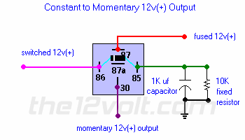
constant to momentary -- posted image.

constant to momentary -- posted image. the12volt • Support the12volt.com
yonubear 
Member - Posts: 11
Member spacespace
Joined: March 05, 2009
Location: North Carolina, United States
Posted: July 28, 2009 at 1:28 PM / IP Logged  
yes it is a polarized cap it is 1000uf 35vdc
the12volt 
Administrator - Posts: 3,955
Administrator spaceThis member has made a donation to the12volt.com. Click here for more info.spaceThis member has been recognized as an authority in Electrical Theory. Click here for more info.spaceThis member has been recognized as an authority in Mobile Audio and Video. Click here for more info.spaceThis member has been recognized as an authority in Mobile Security and Convenience. Click here for more info.spacespace
Joined: March 07, 2002
Location: Louisiana, United States
Posted: July 28, 2009 at 2:50 PM / IP Logged  

Please double check all of  your connections.

30 is the output wire that provides a momentary 12V+ immediately after terminal 86 is connected to 12V+ through a switch (Accessory, Ignition, etc.). Terminal 87 goes to a constant 12V+ source (battery). Terminal 85 is connected to a polarized capacitor and resistor wired in parallel that are each connected to ground as shown in my diagram. Terminal 87a is not used. Pay close attention to the diode across the coil. The cathode side (with stripe) is toward 86. The anode side is toward 85. If necessary, bench check it before installing it in the vehicle. I've used this configuration many times and have never had an issue with it.

constant to momentary -- posted image. the12volt • Support the12volt.com
flybyu 
Member - Posts: 35
Member spacespace
Joined: April 27, 2004
Location: Illinois, United States
Posted: December 11, 2009 at 1:42 AM / IP Logged  
the12volt wrote:

Please double check all of  your connections.

30 is the output wire that provides a momentary 12V+ immediately after terminal 86 is connected to 12V+ through a switch (Accessory, Ignition, etc.). Terminal 87 goes to a constant 12V+ source (battery). Terminal 85 is connected to a polarized capacitor and resistor wired in parallel that are each connected to ground as shown in my diagram. Terminal 87a is not used. Pay close attention to the diode across the coil. The cathode side (with stripe) is toward 86. The anode side is toward 85. If necessary, bench check it before installing it in the vehicle. I've used this configuration many times and have never had an issue with it.

I'd like to go from a constant 12 volt input and as it loses 12 volts it pulses 12 volts to the other side . Is it possiblle?

i am an idiot 
Platinum - Posts: 13,667
Platinum spaceThis member consistently provides reliable informationspace
Joined: September 21, 2006
Location: Louisiana, United States
Posted: December 11, 2009 at 6:30 AM / IP Logged  
flybyu wrote:

I'd like to go from a constant 12 volt input and as it loses 12 volts it pulses 12 volts to the other side . Is it possiblle?

Are you needing a 12volt  pulse when the relay de-energizes?   If so, it will take 2 relays, but I am sure we can figure it out for you.

It would help if we knew your exact application.

lucatz 
Member - Posts: 3
Member spacespace
Joined: January 21, 2010
Location: Quebec, Canada
Posted: January 21, 2010 at 10:12 PM / IP Logged  

Hi,

New forum member looking for some help.

My application requires a 12 volt pulse of 1/2 seconds 50mA. The tricky part is that I need this pulse when the contstant 12v is applied and also when it is removed.

Any help appreciated

Luca

i am an idiot 
Platinum - Posts: 13,667
Platinum spaceThis member consistently provides reliable informationspace
Joined: September 21, 2006
Location: Louisiana, United States
Posted: January 21, 2010 at 11:40 PM / IP Logged  

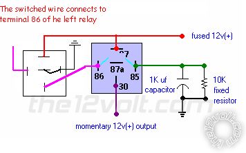
I have a diagram that I think will work for you.  I have not built and tested it yet.  It may take a 2200 mic capacitor.  You will have to build it and test it.  My thinking is that when the left relay is turned on, it will energize the right relay until the capacitor charges, then the right relay will disengage, that will be the piulse when the wire goes positive.  When the wire goes dead, the left relay will now place ground on terminal 86 of the right relay.  The cap wil be charged, thus powering the right relay briefly.  This will be your pulse when the wire goes dead.

In case you missed it earlier, I have not built and tested the above Idea.  You will have to test it before attempting to install it in a vehicle.

You can ditch the resistor, it will not be needed.  Test it and let me know if it works.  Changing the cap size will change the llength of the pulse.

constant to momentary -- posted image.

lucatz 
Member - Posts: 3
Member spacespace
Joined: January 21, 2010
Location: Quebec, Canada
Posted: January 22, 2010 at 7:26 AM / IP Logged  

Thanks I am an idiot,

I will get the parts today and substitute the 1000uF cap for a 2200uF cap and also remove the resistor.

Just to let you know the application is for home theater use. I have a Classe CA-150 that requires a 12 pulse to turn it on and a 12 volt pulse to turn it off remotely. Most components only supply 12v constant nowadays, so this is why I am looking for a solution.

Thanks for your help

Luca

Page of 3

  Printable version Printable version Post ReplyPost New Topic
You cannot post new topics in this forum
You cannot reply to topics in this forum
You cannot delete your posts in this forum
You cannot edit your posts in this forum
You cannot create polls in this forum
You cannot vote in polls in this forum

  •  
Search the12volt.com
Follow the12volt.com Follow the12volt.com on Facebook
Friday, April 26, 2024 • Copyright © 1999-2024 the12volt.com, All Rights Reserved Privacy Policy & Use of Cookies
Disclaimer: *All information on this site ( the12volt.com ) is provided "as is" without any warranty of any kind, either expressed or implied, including but not limited to fitness for a particular use. Any user assumes the entire risk as to the accuracy and use of this information. Please verify all wire colors and diagrams before applying any information.

Secured by Sectigo
the12volt.com spacer
Support the12volt.com
Top
the12volt.com spacer