


2011 Hyundai Sonata Remote Start w/Keyless Pictorial


2011 Hyundai Sonata remote start with keyless entry DIY pictorial.
Notes :
This was a basic U.S. domestic market Sonata GLS. This vehicle has a Factory Alarm and a standard key ( non-PTS ).U.S. market Sonata's without Push To Start do not have a transponder immobilizer system, so no bypass module isnecessary. The Factory FOB's do not work while the engine is running so a R/S system with keyless entry is suggested. The Factory Alarm will not trigger with just a remote start so a Disarm is only necessary with an Unlock or Trunk Release. This vehicle does not have "one touch starting" so it is a candidate for Anti-Grind and Tach Mode starting.Disassembly :
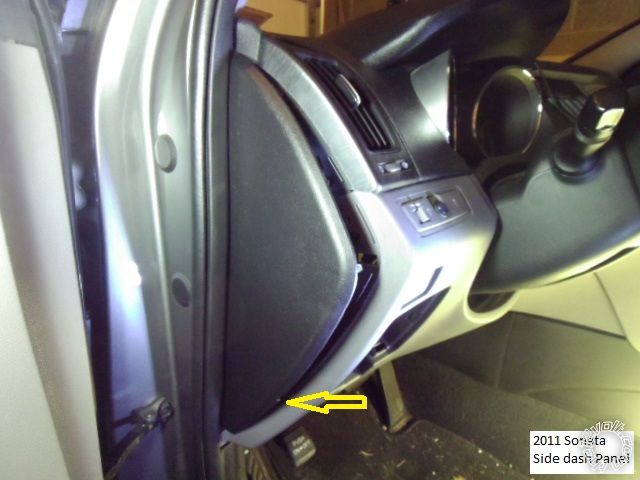
Using a non-marring trim tool, remove the dash side panel. The arrow indicates a notch for trim tool insertion.
Remove the two screws indicated in this photo :
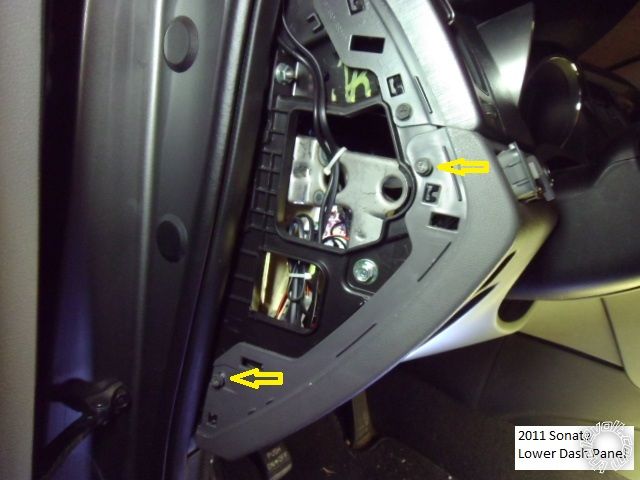
Remove the two screws shown in this picture and release the lower dash panel from the side and then pull straight
away from the dash. The are three retainer clips along the top edge.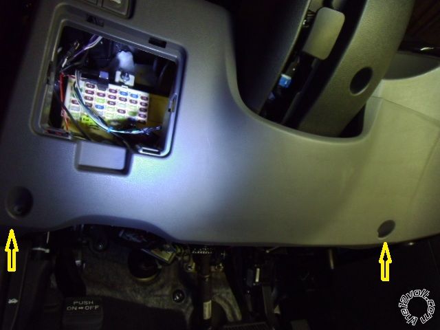
Remove the knee plate by removing the four 10mm bolts shown with Yellow arrows and the one 10mm nut shown
with the orange arrow.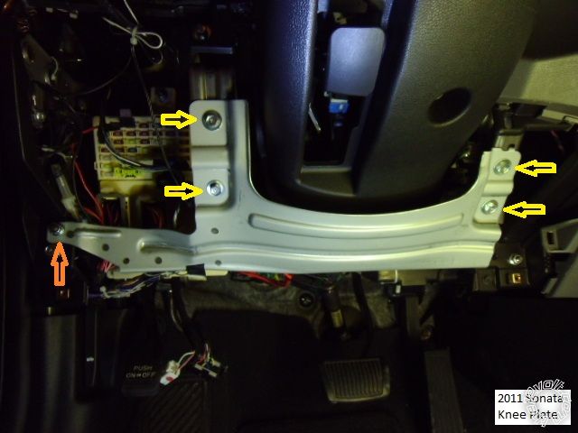
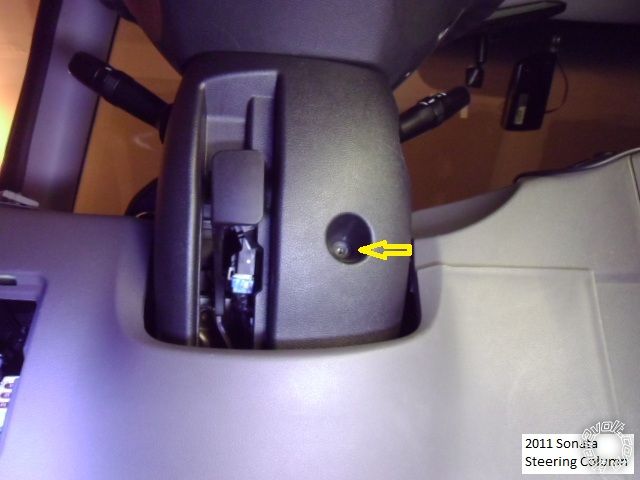
Remove the one screw shown at the underside of the steering column.
Remove two screws located at 3 and 9 O'Clock ( 3 O'Clock shown ). Then separate the upper and lower halves of the
steering column cover and remove both.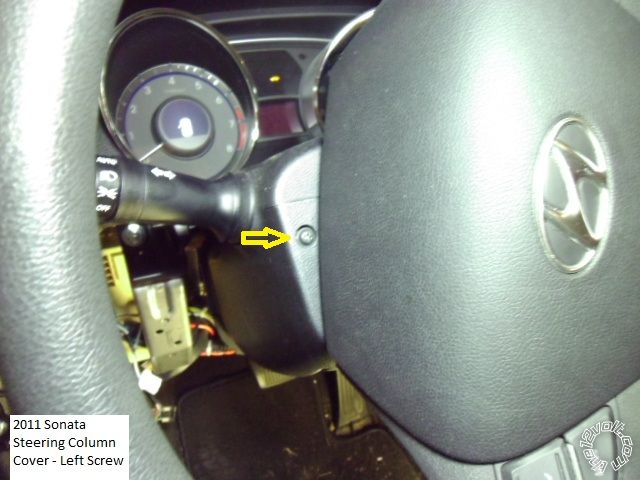
Not shown is the Drivers Kick Panel removal. The hood release lever is remover by compressing the pivot shaft fingers
and pulling the lever straight off the shaft. Remove the door sill trim by lifting it straight up then grasp the DKP and remove it by pulling it back and away.Wiring :
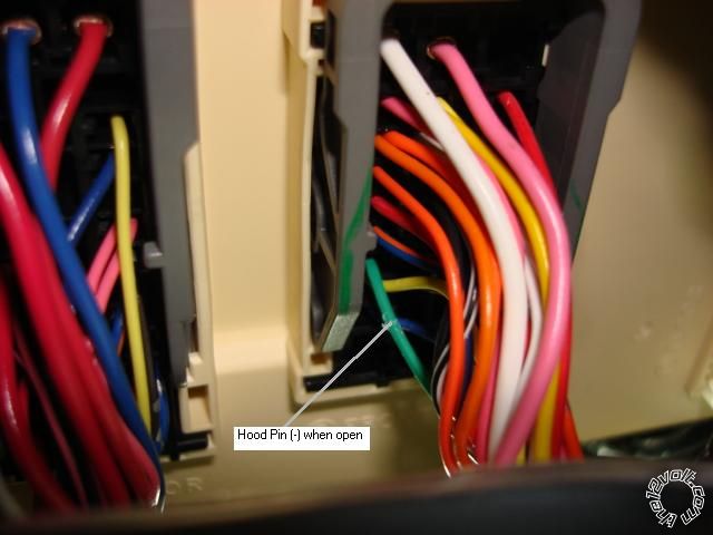
This is a picture of the lower right corner of the dash fuse box. The three wires in the Black plug are an alternate
+12V power source, each at 30 Amps. Close-ups to follow.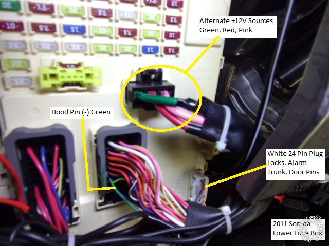
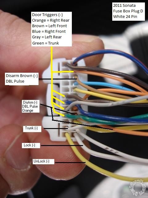
This is a close up of the White 24 Pin Plug with the wire marked.
This is a close-up of the Hood Pin wire.
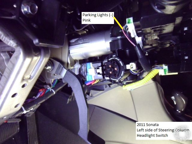
Here is a shot of the left side of the steering column.
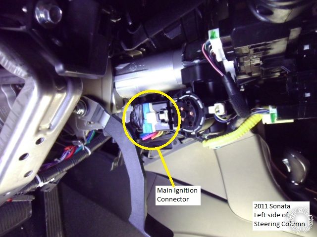
This is a close up of the Main Ignition Harness. Use caution / be gentle when disconnecting this plug, it can cause
the ignition switch to come apart.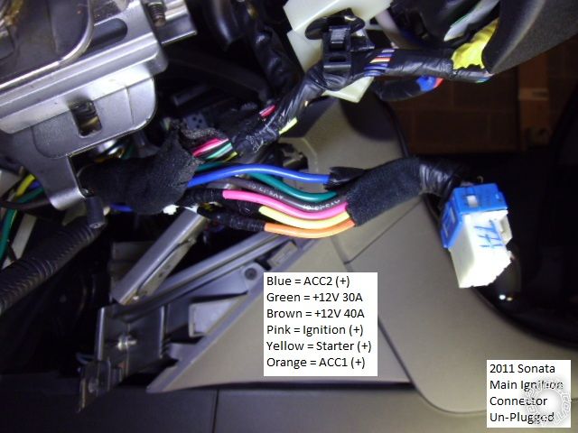
This is a picture of the Keysense wire at the right side of the steering column. Note that the wire color changes
at each side of the connector junction.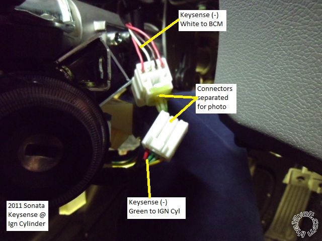
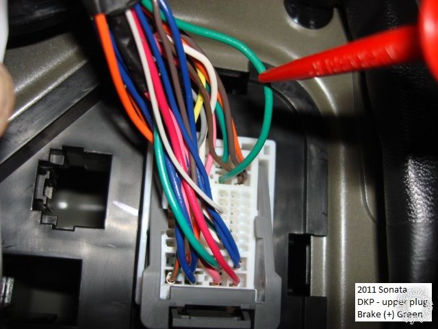
Here is a photo of the Driver Kick Panel area.

The Brake wire is located in the DKP, top plug, pictured below (close-up).
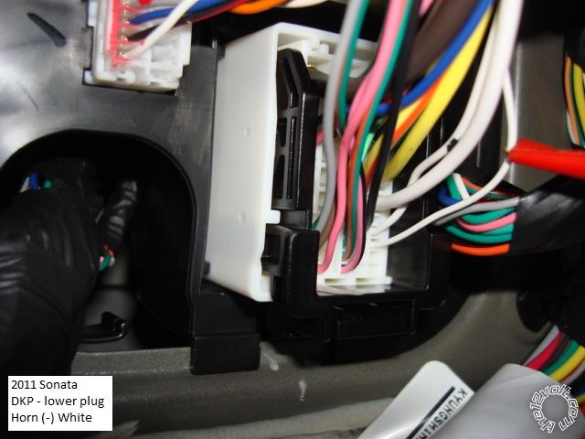
Also in the DKP, bottom plug, is the Horn wire (close-up).
The Parking Lights can be found either at the Headlight Switch connector in the steering column...
or the BCM, which in located under the dash to the right side of the steering column. Also shown is the Rear Defrost
wire and the Auto Headlights wire. The Rear Defrost requires a (-) pulse to turn on and will light the Defrost lightat the console switch. Another pulse will turn it off.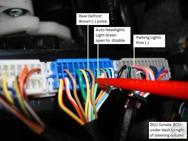
This is a picture of a Tach source, found at any Spark Plug Coil. ( Engine cover removed, lift straight up, retained
by four pins.)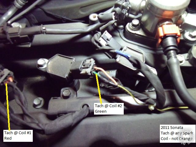
Notes :
There are several large grommets located in the firewall for wire pass thru.On this vehicle, a double pulse to the two Disarm wires ( Orange & Brown ) will also unlock the doors.Soldering is fun!

Hi Frank,
Thanks for catching my error. Somehow I got the two folders mixed up.  ( Teach me to forget the vehicle label in the corner...)
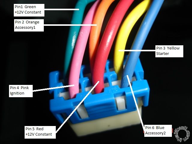
The top picture is correct for the 2011 Sonata. The Sonatas' two +12V constant wires are Green and Brown, both rated at 40 Amps. The second picture is from a 2012 KIA Optima. Aside from the Red vs Brown color change, everything else, including the pin locations on that plug, is the same. Sister cars but slightly different.
Sorry for the confusion, wish I could edit that second picture out.
Kreg
Soldering is fun! Thanks again for the great writeup!!!
OK. The pictorial was on a Sonata GLS with Automatic Transmission. From your description, your car has a Manual Transmission. No
mention was made and your profile info does not give a location but if this is a U.S. market vehicle there will be no transponder based ignition immobilizer system installed. However, if this is a Canadian market vehicle, then it will have a transponder system and need a bypass module.My main issue with this setup is the remote start function. It appears that the Advanced Keys system has no specific Manual Transmission
Reservation Mode like a manual transmission safe remote start system. The Manual Transmission Reservation Mode ensures the vehicle is left in neutral upon vehicle exit and then shuts down the engine and locks the doors. All this is done to prevent the engine from being remote started with the transmission in gear. It's a very important safety issue because the clutch interlock switch must be bypassed to allow a remote start ( the vehicle thinks the clutch is depressed even though there is no one in the vehicle and the clutch pedal is not actually depressed ). Forum rules forbid discussions on installing a non-manual transmission safe remote start system into a manual transmission vehicle. Wedo have an authorized dealer for this product that is an active forum member and perhaps he can shed some light on this product.If the vehicle has a true Neutral Safety signal output, there is a way to do the install. Without that signal, forum rules prevent too much
discussion on this topic / install. Installing the Keyless entry module is fine. Adding the PTS module would be OK as long as you only used it as a PTS switch from inside the car while manually depressing the clutch pedal, not for remote starting.On to the Questions ( I am going by the info in the product install guides, I have never seen / installed / used these items ) :
1.) The vehicle only has one Ignition wire. Your aftermarket system has two available but only one will be needed. Please note that the vehicle has two Accessory wires and the aftermarket system only has one Accessory Output. Additionally the install guide has a cut key blade inserted into the ignition switch and left in the ACC position with the Accessory wire interrupted with a switch. In your case you would need to interrupt two Accessory wires with switches and use an extra external relay to power the second Accessory wire during a PTS.2.) If you have a US market vehicle no bypass module is required and this wire would be "not used".3.) Yes, connect the GWR wire to the Keysense wire shown in the pictorial.4.) NSS Here is where the fun begins. Your vehicle has a manual transmission and to start the vehicle, you must depress the clutch pedal. Your aftermarket system has a remote start capability but IMHO is not actually designed for a Manual Transmission vehicle. Your PTS system should only be installed if you can locate an actual Neutral Safety signal that outputs a (-) signal when the transmission is in neutral. I can not find any wire guide listing for an actual Neutral Safety wire.5.) The Pictorial shows the (-) Parking Light wire and most installers would use a relay to convert the AK104's (+) Parking Light output to the desired (-) signal the vehicle needs. But you can do it another way, using the two AK104 (+) Parking Light wires with this info : Parking Lights (+) GREEN/ Black + (Left), BROWN / Black + (Right) @ dash fuse box, Black 39 pin plug (A), pins 25 and 76.) Your AK104 system does not have a separate Factory Alarm Arm and Disarm output, only Lock and Unlock. This will make it difficult to control these functions. Disarm requires a Double Pulse that is possible with the proper setting of JP3 on the AK104 but will require diodes to split the Unlock output wire into three legs going to three wire locations on the white 24 pin plug shown. Factory Alarm Arm is a whole different story. It will require a SPDT relay and diodes, wired to open a vehicle wire and pulse another, as indicated below : Factory Alarm Arm Yellow and Brown, (-) and open @ dash fuse box, White 24 pin plug (D), pins 15 and 22 Also remember that a Disarm is required before a Trunk Release or the Factory Alarm will be triggered.7.) While the AK104 only has one Door Trigger Input, you should monitor all four doors, the trunk and the hood. To do this split the AK104's Door Trigger Input wire into 6 leads using the standard 1N400x diode ( band towards the AK104 ) and connect to the vehicles trigger wires ( leave JP1 set to - ).Considering all the above, especially the vehicles manual transmission & Factory Alarm and needed relay circuits and diodes, I would suggest
bringing this to a trained / certified installer.Soldering is fun!
kreg357 wrote:
|
mjperk wrote:
|
 Printable version
| You cannot post new topics in this forum You cannot reply to topics in this forum You cannot delete your posts in this forum You cannot edit your posts in this forum You cannot create polls in this forum You cannot vote in polls in this forum |

| Search the12volt.com |

Thursday, May 21, 2026 • Copyright © 1999-2026 the12volt.com, All Rights Reserved • Privacy Policy & Use of Cookies

