the12volt.com spacer
icon

voltage divider with 2 outputs?


Post ReplyPost New Topic
< Prev Topic Next Topic >
dr_harika 
Member - Posts: 8
Member spacespace
Joined: April 19, 2007
Location: Australia
Posted: February 14, 2011 at 8:49 PM / IP Logged  

Hi, I am in the process of designing a circuit for automatic headlights. This has been done before, but I want dual activation (one for parkers, and one for headlights).

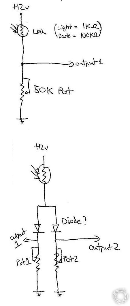
I am using a LDR (light dependent resistor) and have one leg connected to +12v, and one leg connected to a potentiometer to adjust its sensitivity which is connected to ground. The output of the voltage divider is the middle of the two components. This works great, and can trigger one of the circuits with no issues. (see top diagram)
I want to try and use the one LDR and have two separate outputs, which are each controlled by their own pot. (one will be parkers; Semi-Dark, and the other will be headlights on; Dark).
I have tried diodes, but it doesn’t seem to work as I want it to (see bottom diagram)..
Can anyone enlighten me on how to do this? I want to avoid having 2 light sensors, as the light sensor has already been installed in the dash of my car.

Regards Tony.

voltage divider with 2 outputs? -- posted image.

KPierson 
Platinum - Posts: 3,527
Platinum spaceThis member consistently provides reliable informationspace
Joined: April 14, 2005
Location: Ohio, United States
Posted: February 14, 2011 at 9:36 PM / IP Logged  
Run a fixed resistor on the bottom of the voltage divider.
Feed the voltage output of the divider in to two separate op amps. Set each op amp up in a comparator fashion. Each comparator will have it's own pot to adjust sensitivity.
Should work well.
Kevin Pierson
i am an idiot 
Platinum - Posts: 13,693
Platinum spaceThis member consistently provides reliable informationspace
Joined: September 21, 2006
Location: Louisiana, United States
Posted: February 14, 2011 at 10:02 PM / IP Logged  

http://www.bcae1.com/opamp.htm  About 1/3 of the way down the page.  Op Amp as a Comparator

dr_harika 
Member - Posts: 8
Member spacespace
Joined: April 19, 2007
Location: Australia
Posted: February 15, 2011 at 10:25 PM / IP Logged  

Thank you for the heads up and help.

I have ordered a few op-amps, and a few dual op-amps so I can learn with and implement into the circuit.
I will post up the entire circuit with delay feature for comment soon..

The idea is:

One LDR feeding 2 Op amps which drive 2 separate Schmitt triggers (useful for the hysteresis window) which then feed into 2 NPN transistor bases (with caps and pots controlling the time the NPNs stays open (ideally around 30 seconds, so that the lights don’t flick off if subject to a bright light condition at night for a short period of time).


Sorry, you can NOT post a reply.
This topic is closed.

  Printable version Printable version Post ReplyPost New Topic
You cannot post new topics in this forum
You cannot reply to topics in this forum
You cannot delete your posts in this forum
You cannot edit your posts in this forum
You cannot create polls in this forum
You cannot vote in polls in this forum

  •  
Search the12volt.com
Follow the12volt.com Follow the12volt.com on Facebook
Thursday, October 31, 2024 • Copyright © 1999-2024 the12volt.com, All Rights Reserved Privacy Policy & Use of Cookies
Disclaimer: *All information on this site ( the12volt.com ) is provided "as is" without any warranty of any kind, either expressed or implied, including but not limited to fitness for a particular use. Any user assumes the entire risk as to the accuracy and use of this information. Please verify all wire colors and diagrams before applying any information.

Secured by Sectigo
the12volt.com spacer
Support the12volt.com
Top
the12volt.com spacer