the12volt.com spacer
icon

wiring up thermo fan spdt relay


Post ReplyPost New Topic
< Prev Topic Next Topic >
evo180sx 
Member - Posts: 13
Member spacespace
Joined: May 03, 2009
Location: Australia
Posted: May 03, 2009 at 6:09 PM / IP Logged  
Hey Guys,
I have been having issues wiring this thermo fan up.
The LED light on the Fuse is always on when the ignition is off.
The LED light goes off when the car is turned on.
The LED comes on when the thermo switch hits its open ground (90degrees)
The fan does not run...the light just turns on....my radiator is being cooled down by running the heater on full lol, i need help please.
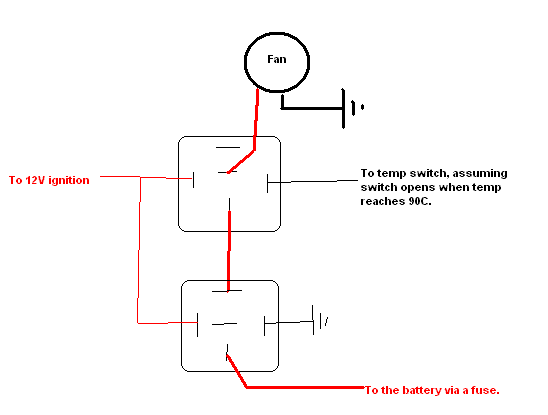
This is a diagram ive made.....this is how im running it at the moment.
wiring up thermo fan spdt relay -- posted image.
Thanks alot
Michael
i am an idiot 
Platinum - Posts: 13,709
Platinum spaceThis member consistently provides reliable informationspace
Joined: September 21, 2006
Location: Louisiana, United States
Posted: May 03, 2009 at 6:18 PM / IP Logged  
Where is the LED connected?   According to your diagram, the fan should be running anytime the ignition switch is off.  And any time the temp is below 90 degrees.  If your fan is not coming on with the ignition off, you have a bad connection somewhere or a faulty fan, relay or fuse.
evo180sx 
Member - Posts: 13
Member spacespace
Joined: May 03, 2009
Location: Australia
Posted: May 03, 2009 at 6:34 PM / IP Logged  
the LED is connect to the inline Fuse...its ment to come on when the Fuse is blown....but its not blown.
How should I wire this up so the fan comes on at 90degrees and only turns on when the ignition is on?....I dont want the fan to run while the car is off as the battery will drain.
And also which wire should I tap into if I want to run a manual switch inside the car so I can run it all the time at the racetrack.
Thanks heaps.
i am an idiot 
Platinum - Posts: 13,709
Platinum spaceThis member consistently provides reliable informationspace
Joined: September 21, 2006
Location: Louisiana, United States
Posted: May 03, 2009 at 6:53 PM / IP Logged  
If it is an AGU type fuse, replace it.   The switch states normally closed, does it open somewhere between 85 and 90C?
evo180sx 
Member - Posts: 13
Member spacespace
Joined: May 03, 2009
Location: Australia
Posted: May 03, 2009 at 6:59 PM / IP Logged  
Nah its not an AGU type fuse.
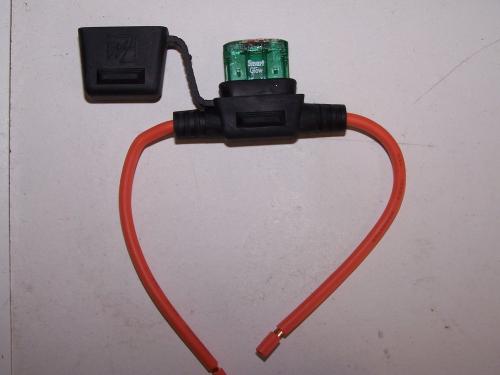
Its the same as this:
wiring up thermo fan spdt relay -- posted image.
but mine has an LED light on the bottom...usually lights up when the fuse is blown, but its not.
i am an idiot 
Platinum - Posts: 13,709
Platinum spaceThis member consistently provides reliable informationspace
Joined: September 21, 2006
Location: Louisiana, United States
Posted: May 03, 2009 at 7:17 PM / IP Logged  
wiring up thermo fan spdt relay -- posted image.
evo180sx 
Member - Posts: 13
Member spacespace
Joined: May 03, 2009
Location: Australia
Posted: May 03, 2009 at 7:17 PM / IP Logged  
Yeah its normally close ground.
The switch opens at 90degrees and the switch closes at 85degrees
I will double check the fuse isn't blown...was hard to tell...very dark at night when i checked.
My diagram should work!
i am an idiot 
Platinum - Posts: 13,709
Platinum spaceThis member consistently provides reliable informationspace
Joined: September 21, 2006
Location: Louisiana, United States
Posted: May 03, 2009 at 7:25 PM / IP Logged  
Your diagram = dead battery in the morning.
evo180sx 
Member - Posts: 13
Member spacespace
Joined: May 03, 2009
Location: Australia
Posted: May 03, 2009 at 8:54 PM / IP Logged  
thanks alot mate :)
fuse was blown too....tried to put a new one
in but blew straight away, the fan tried to run while the car was off with my diagram, i will test out your relay diagram and see how it goes.
thanks :D
i am an idiot 
Platinum - Posts: 13,709
Platinum spaceThis member consistently provides reliable informationspace
Joined: September 21, 2006
Location: Louisiana, United States
Posted: May 03, 2009 at 9:02 PM / IP Logged  
A large cooling fan requires a lot of current to start up. Yeah check my diagram out and let me know if it works.
Page of 3

  Printable version Printable version Post ReplyPost New Topic
You cannot post new topics in this forum
You cannot reply to topics in this forum
You cannot delete your posts in this forum
You cannot edit your posts in this forum
You cannot create polls in this forum
You cannot vote in polls in this forum

  •  
Search the12volt.com
Follow the12volt.com Follow the12volt.com on Facebook
Wednesday, May 14, 2025 • Copyright © 1999-2025 the12volt.com, All Rights Reserved Privacy Policy & Use of Cookies
Disclaimer: *All information on this site ( the12volt.com ) is provided "as is" without any warranty of any kind, either expressed or implied, including but not limited to fitness for a particular use. Any user assumes the entire risk as to the accuracy and use of this information. Please verify all wire colors and diagrams before applying any information.

Secured by Sectigo
the12volt.com spacer
Support the12volt.com
Top
the12volt.com spacer