the12volt.com spacer
icon

how to wire to relay


Post ReplyPost New Topic
< Prev Topic Next Topic >
jsxmike 
Member - Posts: 3
Member spacespace
Joined: November 23, 2012
Location: Texas, United States
Posted: November 23, 2012 at 6:40 PM / IP Logged  

I am trying to connect a Raspberry PI to a relay to control a 12V output.

I have a OMRON G5LA-1 relay.

This is a 5 pin relay. each corner has a pin and one end has a pin in the middle.

The vendor diagram shows them PINS 1-5. 

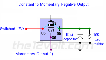
The output driver needs to supply 12V constant output and have a short ground pulse returning back to 12V constant.

I found this diagram for a pulse output: how to wire to relay -- posted image.

Can someone let me know what pins to connect to what?

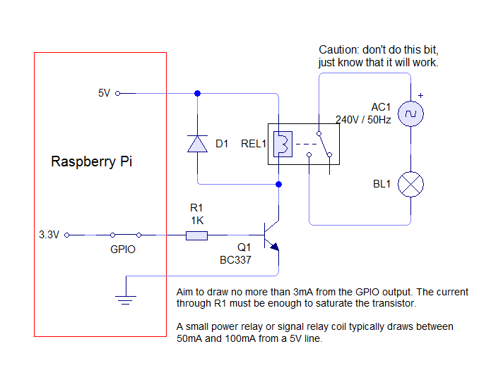
This is the instructions from the Raspberry PI site that shows good informatin - except what pins to connec to what from the relay:

http://www.susa.net/wordpress/2012/06/raspberry-pi-relay-using-gpio/

how to wire to relay -- posted image.

kreg357 
Platinum - Posts: 7,791
Platinum spaceThis member has made a donation to the12volt.com. Click here for more info.spaceThis member has been recognized as an authority in Electrical Theory. Click here for more info.spaceThis member has been recognized as an authority in Mobile Security and Convenience. Click here for more info.spacespace
Joined: January 30, 2009
Location: Pennsylvania, United States
Posted: November 23, 2012 at 7:43 PM / IP Logged  

Here is a link to the OMRON Relay spec sheet : http://components.omron.com/components/web/PDFLIB.nsf/0/4F7D9D9CA026C97E862573930070AC4F/$file/G5LA_E_0911.pdf

The way they have them numbered, looks like pins 2 and 5 are the relays coil.

Relay Pin 2 to Raspberry +5V

Relay Pin 5 to Q1 collector
Relay Pin 3 to AC1
Relay Pin 1 to Motor
Relay Pin 4 not used - insulate

Soldering is fun!
jsxmike 
Member - Posts: 3
Member spacespace
Joined: November 23, 2012
Location: Texas, United States
Posted: November 23, 2012 at 7:55 PM / IP Logged  
Thank you very much.
jsxmike 
Member - Posts: 3
Member spacespace
Joined: November 23, 2012
Location: Texas, United States
Posted: November 23, 2012 at 8:53 PM / IP Logged  

I have drawn up what I think is the right way to merge the two diagrams (inputs and outputs) -- to have the output drive a sustaining 12V until the relay is pulsed, then it will drive GND and revert back to the 12V.

The Raspberry PI is trying to control a driveway gate motor for remote control to activate the gate to open or close.  The INPUT line on the Gate Sensor will activate the motor when it detects a GROUND pulse input.

how to wire to relay -- posted image.

Is this right?

Thank you

howie ll 
Pot Metal - Posts: 16,466
Pot Metal spacespace
Joined: January 09, 2007
Location: United Kingdom
Posted: November 24, 2012 at 1:21 AM / IP Logged  
Your last diagram is correct.
That Omron unit is the standard SPCO format for PCB relays.

Sorry, you can NOT post a reply.
This topic is closed.

  Printable version Printable version Post ReplyPost New Topic
You cannot post new topics in this forum
You cannot reply to topics in this forum
You cannot delete your posts in this forum
You cannot edit your posts in this forum
You cannot create polls in this forum
You cannot vote in polls in this forum

  •  
Search the12volt.com
Follow the12volt.com Follow the12volt.com on Facebook
Sunday, June 9, 2024 • Copyright © 1999-2024 the12volt.com, All Rights Reserved Privacy Policy & Use of Cookies
Disclaimer: *All information on this site ( the12volt.com ) is provided "as is" without any warranty of any kind, either expressed or implied, including but not limited to fitness for a particular use. Any user assumes the entire risk as to the accuracy and use of this information. Please verify all wire colors and diagrams before applying any information.

Secured by Sectigo
the12volt.com spacer
Support the12volt.com
Top
the12volt.com spacer