the12volt.com spacer
icon

paddle shifters for automatic solved


Post ReplyPost New Topic
< Prev Topic Next Topic >
odecious 
Member - Posts: 9
Member spacespace
Joined: January 06, 2006
Location: United States
Posted: January 07, 2006 at 1:06 AM / IP Logged  

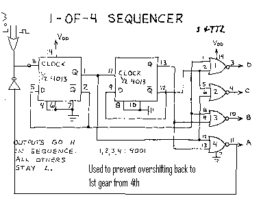
First a safety tip//...next i will show you how to shift down...

paddle shifters for automatic solved -- posted image.

odecious 
Member - Posts: 9
Member spacespace
Joined: January 06, 2006
Location: United States
Posted: January 07, 2006 at 1:26 AM / IP Logged  

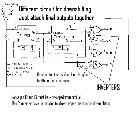
I believe this is a pretty good layout please tell me if you like it

2 different circuits used for upshifting and downshifting, but tie together at a,b,c,d

took me about 2 hours to work all thing out and another to draw

the safety now goes on the 1st gear to stop from shifting to 4th at the red light.paddle shifters for automatic solved -- posted image.

odecious 
Member - Posts: 9
Member spacespace
Joined: January 06, 2006
Location: United States
Posted: January 07, 2006 at 1:28 AM / IP Logged  
odecious wrote:

https://www.the12volt.com/installbay/forum_posts.asp?tid=40671&PN=1&tpn=2

orginal post

First a safety tip//...next i will show you how to shift down...

paddle shifters for automatic solved -- posted image.

hotwaterwizard 
Silver - Posts: 1,350
Silver spacespace
Joined: December 11, 2003
Location: California, United States
Posted: January 07, 2006 at 3:39 PM / IP Logged  
Have you actually hooked up the circuit to see if it actually works?
John DeRosa (Hotwaterwizard)
Stockton California
When in doubt, try it out !
odecious 
Member - Posts: 9
Member spacespace
Joined: January 06, 2006
Location: United States
Posted: January 07, 2006 at 4:02 PM / IP Logged  

no i haven't made a live circuit with this set up, but theortically it will work

if you dont understand any of the concept just ask i will explain

hotwaterwizard 
Silver - Posts: 1,350
Silver spacespace
Joined: December 11, 2003
Location: California, United States
Posted: January 07, 2006 at 6:23 PM / IP Logged  

You do realize that you have just complicated the circuit so it now uses 4 IC's.

The OR on the input

The Flip-Flops

The NOR Gates and

The Inverters

I am working out the New Circuit

Here is what I have so far.

paddle shifters for automatic solved -- posted image.

John DeRosa (Hotwaterwizard)
Stockton California
When in doubt, try it out !
odecious 
Member - Posts: 9
Member spacespace
Joined: January 06, 2006
Location: United States
Posted: January 07, 2006 at 10:38 PM / IP Logged  

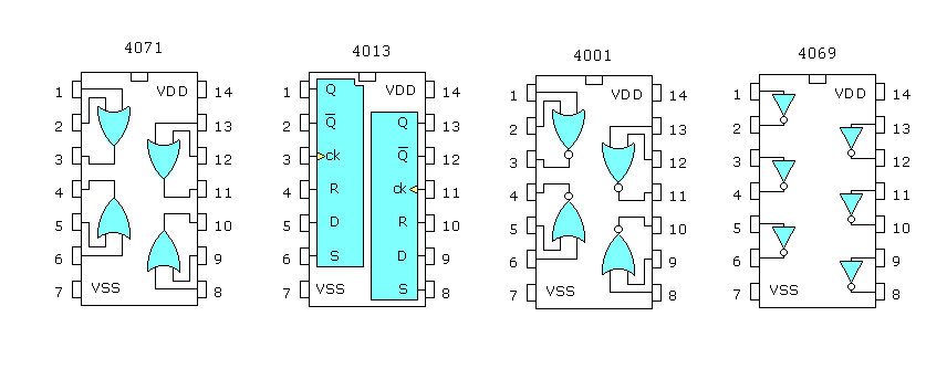
you actually must have 6 ic's all together

up and down ic will be

up must have 1 OR(1/4 chip), 2 Flip Flops(1 chip), 4 NOR's(1 chip), and 0 inverters

down must have 1 OR(1/4 chip),2 Flip Flops(1 chip), 4 NOR's(1 chip), and 2 inverters(1/3 chip)

by these terms you can use 1(4071 chip), 2(4013 chips) 2(4001 chips) and 1(4069 chip)

you can not use the same flip flop or nor gate chips due to high/low conflict "which low generally wins"

i would draw it if you would like.


odecious 
Member - Posts: 9
Member spacespace
Joined: January 06, 2006
Location: United States
Posted: January 07, 2006 at 10:42 PM / IP Logged  

sorry on the up circuit you need 1 inverter on the safety loop but the same 4069 can be used

and also one extra on the down circuit for the same reason

nonetheless you can use the same 4069 for the whole circuit

total of 4 inverters

hotwaterwizard 
Silver - Posts: 1,350
Silver spacespace
Joined: December 11, 2003
Location: California, United States
Posted: January 08, 2006 at 12:52 AM / IP Logged  

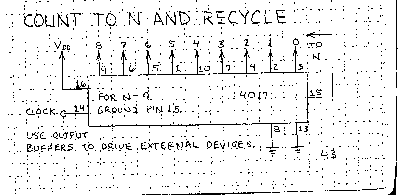
Here is an easier solution

paddle shifters for automatic solved -- posted image.

John DeRosa (Hotwaterwizard)
Stockton California
When in doubt, try it out !
KPierson 
Platinum - Posts: 3,527
Platinum spaceThis member consistently provides reliable informationspace
Joined: April 14, 2005
Location: Ohio, United States
Posted: January 08, 2006 at 2:03 AM / IP Logged  

In the two hours it took you to think that up I could have programmed a microcontroller to acomplish what you are going after, but with only ONE chip total.  It actually sounds like a fun project, let me know if you would like my help.  I could easily have it programmed, tested, and shipped within a few days.

Kevin Pierson
Page of 2

  Printable version Printable version Post ReplyPost New Topic
You cannot post new topics in this forum
You cannot reply to topics in this forum
You cannot delete your posts in this forum
You cannot edit your posts in this forum
You cannot create polls in this forum
You cannot vote in polls in this forum

  •  
Search the12volt.com
Follow the12volt.com Follow the12volt.com on Facebook
Friday, July 4, 2025 • Copyright © 1999-2025 the12volt.com, All Rights Reserved Privacy Policy & Use of Cookies
Disclaimer: *All information on this site ( the12volt.com ) is provided "as is" without any warranty of any kind, either expressed or implied, including but not limited to fitness for a particular use. Any user assumes the entire risk as to the accuracy and use of this information. Please verify all wire colors and diagrams before applying any information.

Secured by Sectigo
the12volt.com spacer
Support the12volt.com
Top
the12volt.com spacer