


2004 mazda mpv sliding door info
Home /
the12volt's Install Bay /
Vehicle Wiring Information & File Requests / 2004 mazda mpv sliding door info ( Topic Closed)


Posted: November 22, 2008 at 3:14 PM / IP Logged

Posted: November 23, 2008 at 8:04 PM / IP Logged
Posted: November 26, 2008 at 6:31 PM / IP Logged
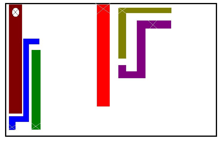 This is the inside of the switch and how the PCB is laid out. The X's are where i soldered the wires. Take note that this is very risky, and specifically keep in mind your connections must be near the top or bottom to allow the internal parts to still move freely. Be careful when taking the switch apart as well the contacts have a small detent ball and spring to maintain pressure. DO NOT lose them! lol
I also ended up using 4 relays to simply make contact because putting ground and also resistance did nothing. Basically like i said i just simulated making contact the way the switches do. Also you may want to have some dielectric grease handy as you will need to clean the PCB before soldering, and not having grease inside will cause the switches to stick.
I truely hope this helps someone!
This is the inside of the switch and how the PCB is laid out. The X's are where i soldered the wires. Take note that this is very risky, and specifically keep in mind your connections must be near the top or bottom to allow the internal parts to still move freely. Be careful when taking the switch apart as well the contacts have a small detent ball and spring to maintain pressure. DO NOT lose them! lol
I also ended up using 4 relays to simply make contact because putting ground and also resistance did nothing. Basically like i said i just simulated making contact the way the switches do. Also you may want to have some dielectric grease handy as you will need to clean the PCB before soldering, and not having grease inside will cause the switches to stick.
I truely hope this helps someone!Sorry, you can NOT post a reply.
This topic is closed.
 Printable version
| You cannot post new topics in this forum You cannot reply to topics in this forum You cannot delete your posts in this forum You cannot edit your posts in this forum You cannot create polls in this forum You cannot vote in polls in this forum |

| Search the12volt.com |
Follow the12volt.com 
Wednesday, April 1, 2026 • Copyright © 1999-2026 the12volt.com, All Rights Reserved • Privacy Policy & Use of Cookies

Wednesday, April 1, 2026 • Copyright © 1999-2026 the12volt.com, All Rights Reserved • Privacy Policy & Use of Cookies
Disclaimer:
*All information on this site ( the12volt.com ) is provided "as is" without any warranty of any kind, either expressed or implied, including but not limited to fitness for a particular use. Any user assumes the entire risk as to the accuracy and use of this information. Please
verify all wire colors and diagrams before applying any information.
