


 I have fabricated the mechanism to operate the camera screen door using the RDP...
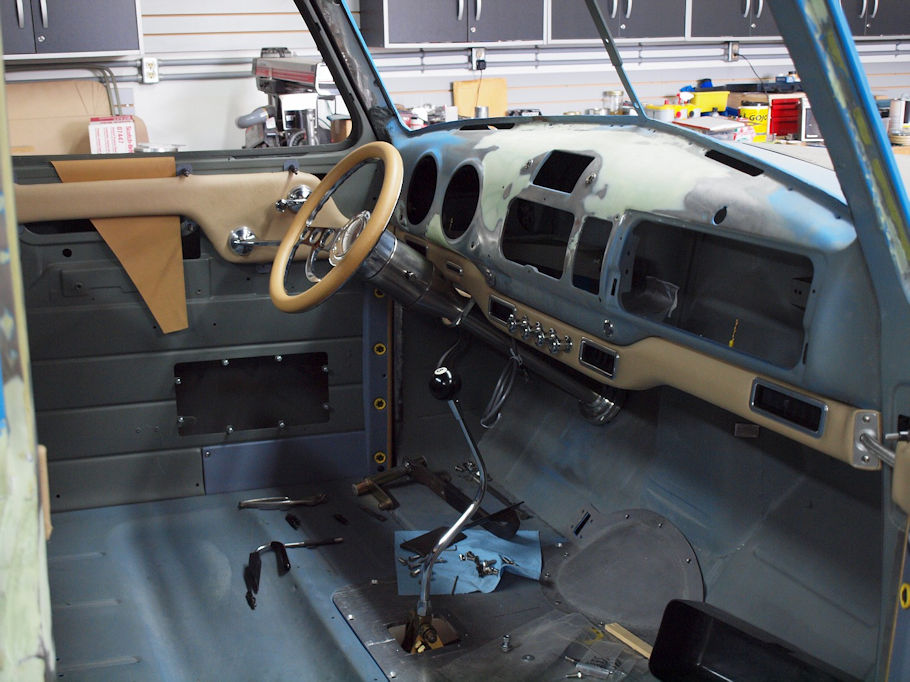
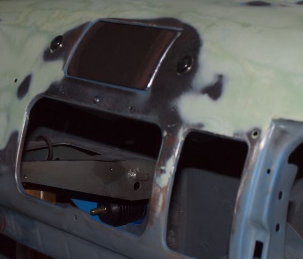
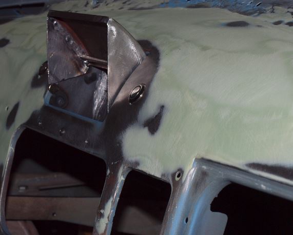
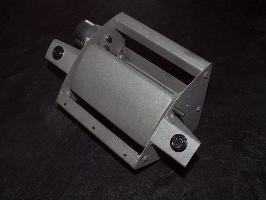 ... and it fits under the dash and opens the Radio Delete Plate to show the 4.3" rear view camera screen.
 What I DESPERATELY need is a schematic to make it work automatically...
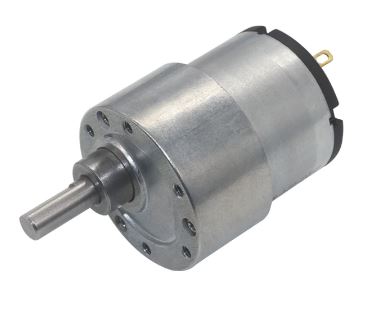
- The motor to open the door is 12 volt.
- The motor is reversible
- The signal to open the camera screen will come from the back up lights (tranny in reverse)
- The signal to close the RDP once the tranny is removed from reverse gear.
What do I need to stop the travel of the RDP opening? A relay, a micro switch?
What to I need to reverse the process and close the RDP once the transmission is out of reverse? Some sort of polarity switch, another relay and another micro switch to stop it's downward travel?
You can email me directly if you need more information...
Any help would be GREATLY appreciated.
52-Chebby
What I DESPERATELY need is a schematic to make it work automatically...
- The motor to open the door is 12 volt.
- The motor is reversible
- The signal to open the camera screen will come from the back up lights (tranny in reverse)
- The signal to close the RDP once the tranny is removed from reverse gear.
What do I need to stop the travel of the RDP opening? A relay, a micro switch?
What to I need to reverse the process and close the RDP once the transmission is out of reverse? Some sort of polarity switch, another relay and another micro switch to stop it's downward travel?
You can email me directly if you need more information...
Any help would be GREATLY appreciated.
52-Chebby

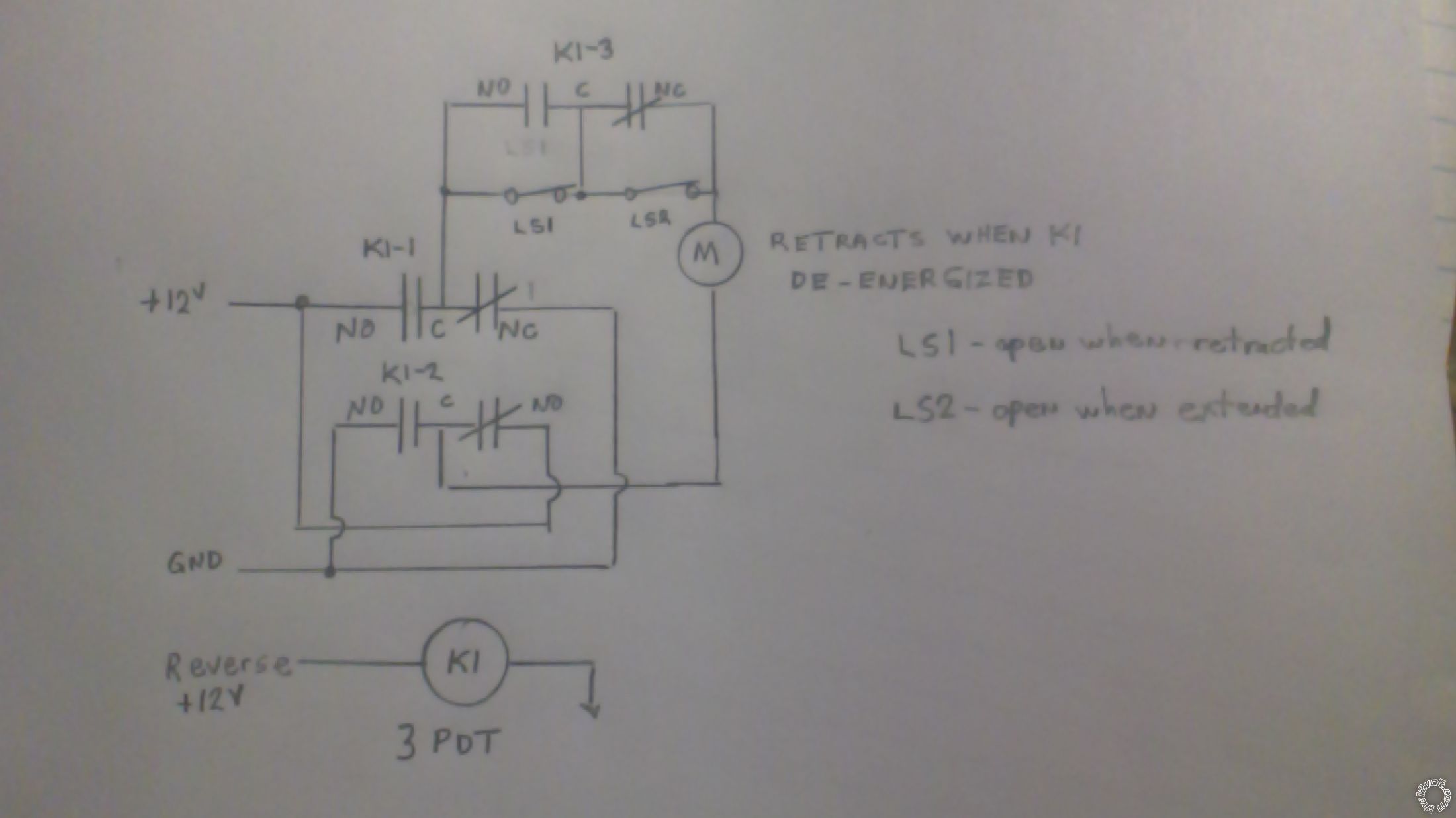 LS1, LS2 - are NC switches which become open reaching the retracted and extended positions (respectively);
M - is your gear motor - connected so that it rotates towards retracted when K1 coil is not energized by reverse 12V;
K1 - is a 3PDT relay (or 2 DPDT relays if easier to source);
Check out my logic on this.
When retracted, LS1 and K1-3 NO contacts are open so motor is not powered.
When reverse energizes coil of K1, K1-3 NO contacts close and bypass LS1. Motor rotates towards extended position until LS2 is activated (opened). Motor stops.
When reverse 12V drops off, K1-3 NC contacts close to bypass the open LS2 switch. Motor rotates towards retracted position until LS1 is activated (opened). Motor stops.
LS1, LS2 - are NC switches which become open reaching the retracted and extended positions (respectively);
M - is your gear motor - connected so that it rotates towards retracted when K1 coil is not energized by reverse 12V;
K1 - is a 3PDT relay (or 2 DPDT relays if easier to source);
Check out my logic on this.
When retracted, LS1 and K1-3 NO contacts are open so motor is not powered.
When reverse energizes coil of K1, K1-3 NO contacts close and bypass LS1. Motor rotates towards extended position until LS2 is activated (opened). Motor stops.
When reverse 12V drops off, K1-3 NC contacts close to bypass the open LS2 switch. Motor rotates towards retracted position until LS1 is activated (opened). Motor stops.If you wish to post a reply to this topic, you must first login.
If you are not already registered, you must first register.
 Printable version


| You cannot post new topics in this forum You cannot reply to topics in this forum You cannot delete your posts in this forum You cannot edit your posts in this forum You cannot create polls in this forum You cannot vote in polls in this forum |

| Search the12volt.com |
Follow the12volt.com 
Tuesday, April 21, 2026 • Copyright © 1999-2026 the12volt.com, All Rights Reserved • Privacy Policy & Use of Cookies

Tuesday, April 21, 2026 • Copyright © 1999-2026 the12volt.com, All Rights Reserved • Privacy Policy & Use of Cookies
Disclaimer:
*All information on this site ( the12volt.com ) is provided "as is" without any warranty of any kind, either expressed or implied, including but not limited to fitness for a particular use. Any user assumes the entire risk as to the accuracy and use of this information. Please
verify all wire colors and diagrams before applying any information.
