the12volt.com spacer
icon

Ground when armed output...


Post ReplyPost New Topic
< Prev Topic Next Topic >
eloshdesign 
Member - Posts: 15
Member spacespace
Joined: March 24, 2002
Location: United States
Posted: March 25, 2002 at 10:42 AM / IP Logged  
Could somebody tell me how to hook up a relay so when my alarm arms, my two actuators go down?
I have a power window type switch that controls the actuators manually. I have 2 extension leads from the actuator motor wires ready to hook up to my alarm's ground when armed output (ORANGE on a Prestige APS995). I tried something yesterday and it did not work and caused weird stuff to happen when hooked up. So I unplugged the relay.
So now I need to know what goes where, so when it arms, the actuators go down (nothing at disarm though).
Thanks,
Daren
the12volt 
Administrator - Posts: 3,955
Administrator spaceThis member has made a donation to the12volt.com. Click here for more info.spaceThis member has been recognized as an authority in Electrical Theory. Click here for more info.spaceThis member has been recognized as an authority in Mobile Audio and Video. Click here for more info.spaceThis member has been recognized as an authority in Mobile Security and Convenience. Click here for more info.spacespace
Joined: March 07, 2002
Location: Louisiana, United States
Posted: March 25, 2002 at 11:46 AM / IP Logged  

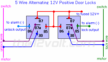
Hi eloshdesign, if you are attempting to wire directly to the actuators, use the diagram below with the door lock outputs from your APS995 (should be the red and green wires in a two connector plug) and pay close attention to the switch and motor sides of each lead going to the actuators. You can not simply tap into the two actuator leads as you described:

Ground when armed output... -- posted image.

https://www.the12volt.com/doorlocks/page3.asp#5w

If you do not want to unlock the doors, then you only need to use one relay to lock them and you can disregard the other reIay shown for unlocking.

f you need more help, let us know.

the12volt


eloshdesign 
Member - Posts: 15
Member spacespace
Joined: March 24, 2002
Location: United States
Posted: March 25, 2002 at 12:10 PM / IP Logged  
Thank you the12volt,
If I want the actuators to ONLY go down during arm and NOT go up during disarm, wouldn't I just use the lock side (right side) of the above diagram?
I see that the wire from the switch to the motor must go through the relay... does that mean that the switch will only function during disarm (which would be fine)?
Could I ask you another question?
I want to also use the remote (channel 6 LT BLUE/BLACK and channel 7 LT BLUE/RED) to raise and lower the actuators. What would that diagram look like?
Thanks!
the12volt 
Administrator - Posts: 3,955
Administrator spaceThis member has made a donation to the12volt.com. Click here for more info.spaceThis member has been recognized as an authority in Electrical Theory. Click here for more info.spaceThis member has been recognized as an authority in Mobile Audio and Video. Click here for more info.spaceThis member has been recognized as an authority in Mobile Security and Convenience. Click here for more info.spacespace
Joined: March 07, 2002
Location: Louisiana, United States
Posted: March 25, 2002 at 12:19 PM / IP Logged  

Hi eloshdesign, like I said in the post above.." If you do not want to unlock the doors, then you only need to use one relay to lock them and you can disregard the other reIay shown for unlocking. " The switch will continue to work as it does now locking and unlocking the doors.

The relay diagram will be the same to use your other channels to lock and unlock the doors. Connect one of your outputs to the coil of the lock relay and the other to the coil of the unlock relay where it shows "to alarm (-) lock output" and " to alarm (-) unlock output" respectively instead of using the door lock outputs from the alarm. 

the12volt


Sorry, you can NOT post a reply.
This topic is closed.

  Printable version Printable version Post ReplyPost New Topic
You cannot post new topics in this forum
You cannot reply to topics in this forum
You cannot delete your posts in this forum
You cannot edit your posts in this forum
You cannot create polls in this forum
You cannot vote in polls in this forum

  •  
Search the12volt.com
Follow the12volt.com Follow the12volt.com on Facebook
Tuesday, June 11, 2024 • Copyright © 1999-2024 the12volt.com, All Rights Reserved Privacy Policy & Use of Cookies
Disclaimer: *All information on this site ( the12volt.com ) is provided "as is" without any warranty of any kind, either expressed or implied, including but not limited to fitness for a particular use. Any user assumes the entire risk as to the accuracy and use of this information. Please verify all wire colors and diagrams before applying any information.

Secured by Sectigo
the12volt.com spacer
Support the12volt.com
Top
the12volt.com spacer