


2014 Kia Forte Remote Start Install Pictorial
Home /
the12volt's Install Bay /
Car Security and Convenience - Alarm/Remote Start Pictorials / 2014 Kia Forte Remote Start Install Pictorial ( Topic Closed)


Posted: January 23, 2014 at 9:38 AM / IP Logged
 Left side dash cover is held in with Plastic clips Use a non marring tool to remove
 There is 2 Phillps screws under the cover that hold in the left side of the dash
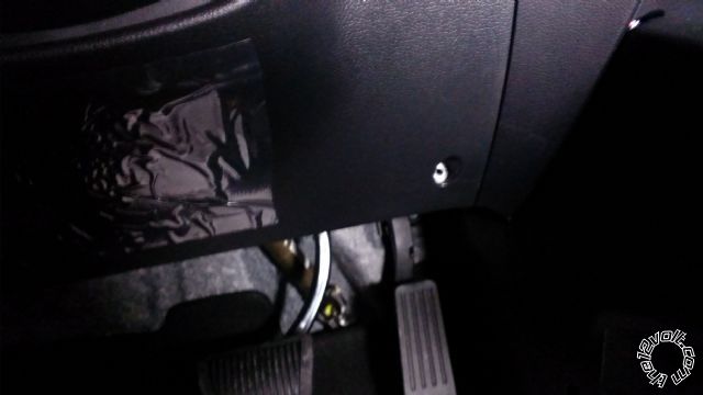 There is 1 phillps screw in the right side of the dash
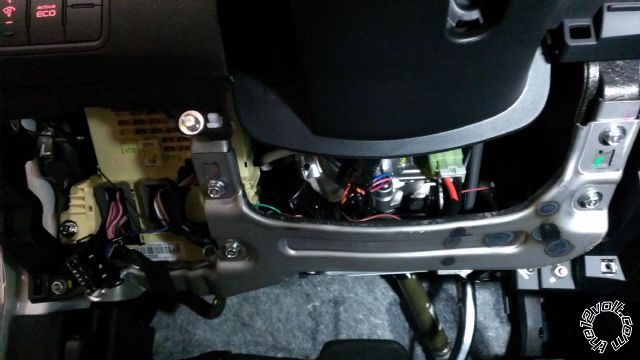 The Metal is held in by 5 10mm Bolts
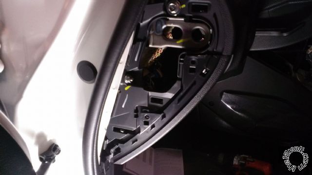
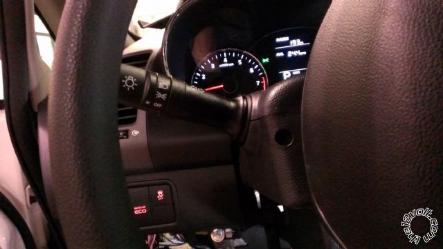 Turn the steering wheel to the left to expose 1 phillps screw
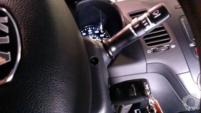 Turn the steering wheel to the right to expose 1 phillps screw
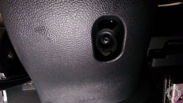 The bottom of the column shroud has 1 phillps screw
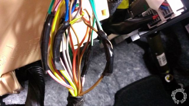
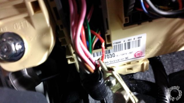
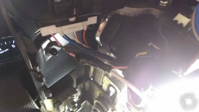
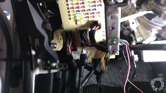 Overall fusebox view bottom right connector is where the locks,FAD,drivers door pin, The black clip hanging is where the hood pin wire is located
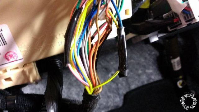
 Drivers Door Pin (Brown) Pin 1 This was used with the rearm wire to shut down the auto lights
 Factory alarm disarm (pink) pin 17
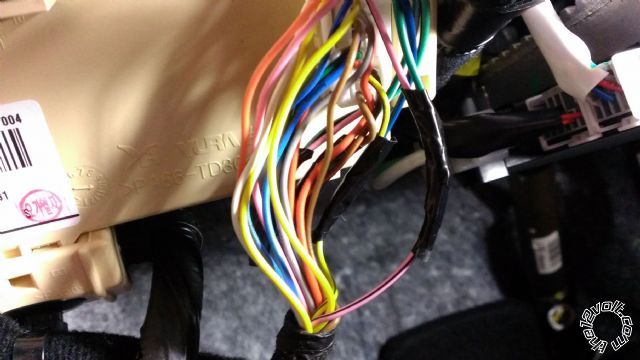 Lock Type B(Pink/Black) Pin 12
 Unlock Type B (yellow/Black) Pin 3
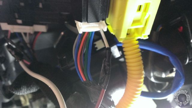
 Trunk release Fusebox Left side connector Pin 35 (this is the motor wire you will need a relay to invert the polarity if your unit doesnt have the capability)
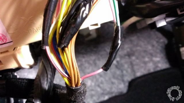
 Factory hood Pin Fusebox black 30 pin plug (D) (Green) Pin 15
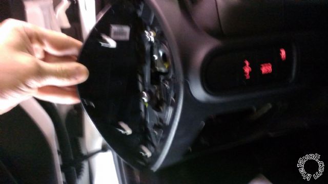
 Horn (white) at Clock spring connector
 12 volts (green) Pin 1 Ingition Harness
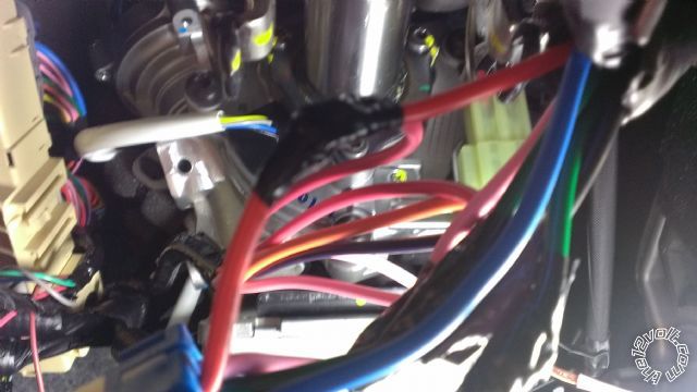 12 Volts (red) Pin 5 Ingition Harness
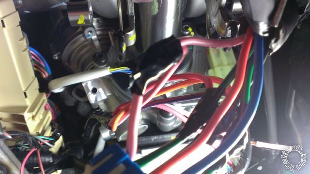 Ingition (pink) Pin 4 Ingition Harness
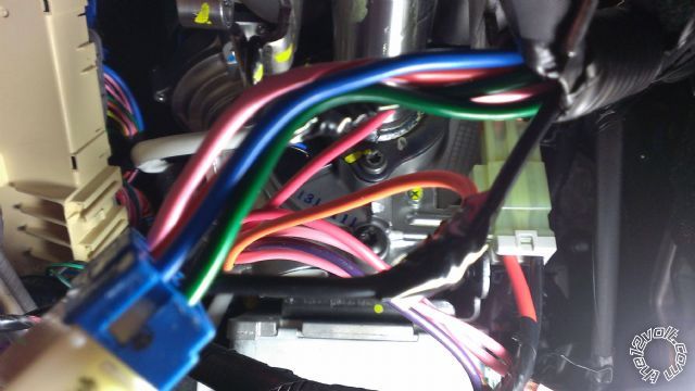 Acc 1 (black) Pin 2 Ingition Harness
 Acc 2 (Blue) Pin 6 Ingition Harness
 Starter ( Green) Pin 3 Ingition Harness
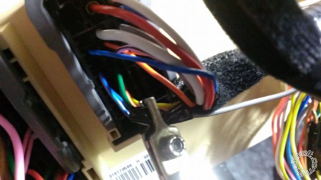
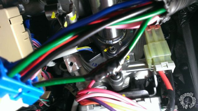
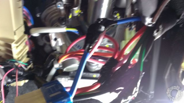
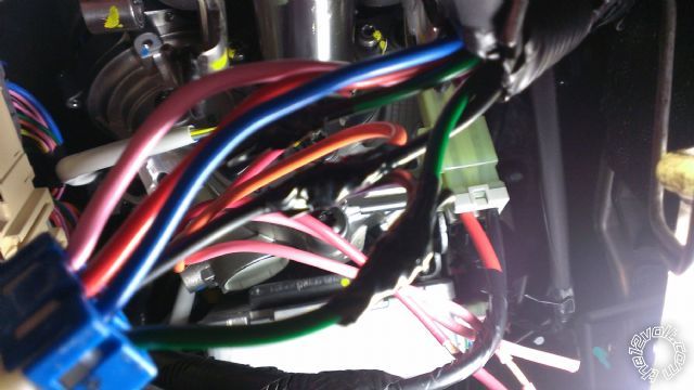
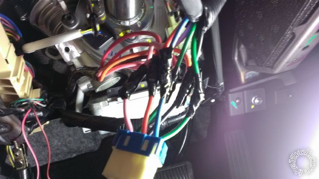 Overall Ingition View
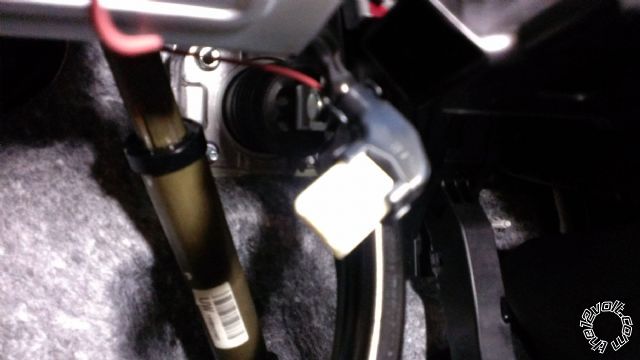 Brake theres a plastic shroud covering the end of the wires its comes right off with a few clips
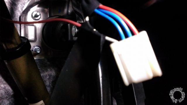 Brake wire without the Shroud on it (gray)
 Negitive Parking lights (pink) Pin 2 at light switch
Whats not shown is the ground Plenty of room in the kick panel for that and the Tach Any uncommon side of a coil or injector will work
Negitive Parking lights (pink) Pin 2 at light switch
Whats not shown is the ground Plenty of room in the kick panel for that and the Tach Any uncommon side of a coil or injector will work

Posted: February 21, 2014 at 11:48 AM / IP Logged
Posted: February 21, 2014 at 12:02 PM / IP Logged

Posted: July 12, 2014 at 5:36 PM / IP Logged
Posted: November 01, 2014 at 5:48 PM / IP Logged
Posted: June 23, 2015 at 6:32 PM / IP Logged
Posted: June 24, 2015 at 6:52 AM / IP Logged
Posted: June 24, 2015 at 9:40 AM / IP Logged
Posted: April 02, 2017 at 7:11 PM / IP Logged
Posted: July 28, 2017 at 11:10 AM / IP Logged
Sorry, you can NOT post a reply.
This topic is closed.
 Printable version
| You cannot post new topics in this forum You cannot reply to topics in this forum You cannot delete your posts in this forum You cannot edit your posts in this forum You cannot create polls in this forum You cannot vote in polls in this forum |

| Search the12volt.com |
Follow the12volt.com 
Sunday, April 19, 2026 • Copyright © 1999-2026 the12volt.com, All Rights Reserved • Privacy Policy & Use of Cookies

Sunday, April 19, 2026 • Copyright © 1999-2026 the12volt.com, All Rights Reserved • Privacy Policy & Use of Cookies
Disclaimer:
*All information on this site ( the12volt.com ) is provided "as is" without any warranty of any kind, either expressed or implied, including but not limited to fitness for a particular use. Any user assumes the entire risk as to the accuracy and use of this information. Please
verify all wire colors and diagrams before applying any information.
