the12volt.com spacer
icon

autopage, mercury mariner 2007


Post ReplyPost New Topic
< Prev Topic Next Topic >
and0b 
Member - Posts: 27
Member spacespace
Joined: October 29, 2010
Location: Illinois, United States
Posted: October 31, 2010 at 1:18 PM / IP Logged  
I need some help with my Autopage Remote Starter installation. In the installation manual(http://carmedia1.com/pdf/RSTKE900.pdf) they say so VIOLET wire should be connected to the low current start solenoid
wire of the ignition switch harness, between START CUT RELAY and NEUTRAL SAFETY SWITCH(see picture).
autopage, mercury mariner 2007 -- posted image.
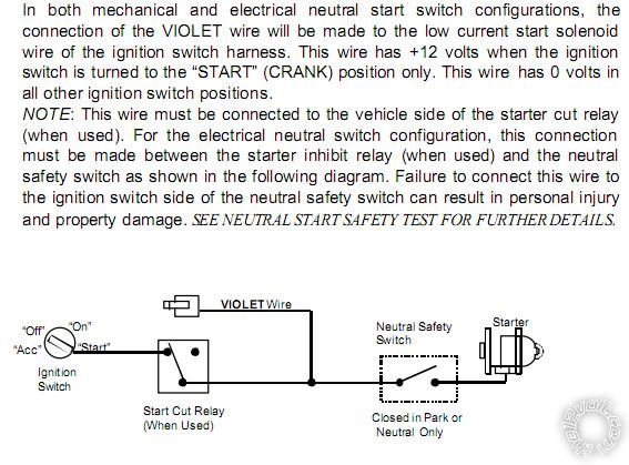
My question is: Do I have START CUT RELAY in my car and if I will connect this wire to the wire around the steering column(not sure yet which one: "Starter Positive Wire (+): Tan/Light Blue" or "Vehicle Ignition Wire (+): WHITE/ orange"), it will be before NSS?
Thank you!
Andrew
howie ll 
Pot Metal - Posts: 16,466
Pot Metal spacespace
Joined: January 09, 2007
Location: United Kingdom
Posted: October 31, 2010 at 2:52 PM / IP Logged  
A basic answer, the neutral safety switch is only there on auto transmission vehicles. For your purposes the violet goes to the vehicle starter wire, tan/light blue.
and0b 
Member - Posts: 27
Member spacespace
Joined: October 29, 2010
Location: Illinois, United States
Posted: October 31, 2010 at 3:02 PM / IP Logged  
Thank you Howie,
but do you know if 2007 Mercury mariner has a START CUT RELAY???
Andrew
Mike M2 
Platinum - Posts: 2,652
Platinum spacespace
Joined: June 29, 2005
Location: United States
Posted: October 31, 2010 at 3:22 PM / IP Logged  
The starter cut relay would be part of an aftermarket alarm. If you don't have one, simply connect as Howie states. Don't overthink it...
Mike M2
Tech Manager
CS Dealer Services
and0b 
Member - Posts: 27
Member spacespace
Joined: October 29, 2010
Location: Illinois, United States
Posted: October 31, 2010 at 4:00 PM / IP Logged  
Thank you for quick answer. I have more questions if I can...
Brown wire should be connected to accessory output:
"Brown Wire –Accessory Output (Heater /AC Output)
Connect the BROWN wire to the accessory wire in the vehicle that powers the
climate control system.    7
An accessory wire will show + 12 volts when the ignition switch is turned to the
“ACCESSORY” or “ON” and “RUN” positions, and will show 0 Volts when the
key is turned to the “OFF” and “START” or “CRANK” position. There will often
be more than one accessory wire in the ignition harness. The correct
accessory wire will provide power to the vehicle’s climate control system. Some
vehicles may have separate wires for the blower motor and the air conditioning
compressor. In such cases, it will be necessary to add a relay to power the
second accessory wire. "
Do you know if my car needs a relay?
Andrew
howie ll 
Pot Metal - Posts: 16,466
Pot Metal spacespace
Joined: January 09, 2007
Location: United Kingdom
Posted: October 31, 2010 at 4:15 PM / IP Logged  
if you have only one ACC wire, then no.
and0b 
Member - Posts: 27
Member spacespace
Joined: October 29, 2010
Location: Illinois, United States
Posted: October 31, 2010 at 4:41 PM / IP Logged  
How I can tell if I have one or two wires???
howie ll 
Pot Metal - Posts: 16,466
Pot Metal spacespace
Joined: January 09, 2007
Location: United Kingdom
Posted: October 31, 2010 at 5:51 PM / IP Logged  
Test. Q., are you up for this?
and0b 
Member - Posts: 27
Member spacespace
Joined: October 29, 2010
Location: Illinois, United States
Posted: October 31, 2010 at 6:08 PM / IP Logged  
Hello everybody!!!
Anyone of you is familiar with AutoPage remote Starters systems like C3-RSTKE-900 ??? Here is it's install manual:
http://carmedia1.com/pdf/RSTKE900.pdf
I have some doubts reading this manual like on page 9 - about connector H10, pin #3:
"H10/3 Pink wire – (-) 200mA Programmable Output   
2 Steps Unlock Output (Factory default setting)   
(See System Feature C – 1 Programming)   
The 2 steps unlock feature will work for the most fully electronic door lock circuit. The vehicle must have an electronic door lock switch (not the lock knob or key switch), which locks and unlocks all of vehicle's doors. When wired for this feature, press the disarm (or unlock) button one time will disarm the system and unlock the driver's door only. If, press disarm (or unlock) button two times within 3 seconds, the system will disarm and all doors will unlock.
   Factory Security Disarm Signal Output –
This wire is designed to disarm a factory installed security system. This wire sends a negative (-) 1 seconds pulse upon a remote start and remote door unlocking. Some factory systems must be disarmed to allow remote starting. In most cases, this wire may be connected directly to the factory alarm disarm wire. The correct wire will show negative ground when the key is used to unlock the doors or trunk. This wire is usually found in the kick panel area in the wiring harness coming into the car body from the door.
Start Status (Shock Sensor By-Pass Control) Output–   
This wire is designed to by-pass shock sensor module. This wire will supply an output at all times the remote start is operating plus an additional 3 seconds after the remote start unit turn off. "
and page 16, H7 3pin connector:
autopage, mercury mariner 2007 -- posted image.
and next pages.
I'm not sure how to interpret it and how to wire it.
Thank you for any help.
Andrew
and0b 
Member - Posts: 27
Member spacespace
Joined: October 29, 2010
Location: Illinois, United States
Posted: October 31, 2010 at 7:04 PM / IP Logged  
howie ll wrote:
Test. Q., are you up for this?
Yes!
Where to look for it, in ignition harnes??? there is 17wires.
Page of 4

  Printable version Printable version Post ReplyPost New Topic
You cannot post new topics in this forum
You cannot reply to topics in this forum
You cannot delete your posts in this forum
You cannot edit your posts in this forum
You cannot create polls in this forum
You cannot vote in polls in this forum

  •  
Search the12volt.com
Follow the12volt.com Follow the12volt.com on Facebook
Monday, June 10, 2024 • Copyright © 1999-2024 the12volt.com, All Rights Reserved Privacy Policy & Use of Cookies
Disclaimer: *All information on this site ( the12volt.com ) is provided "as is" without any warranty of any kind, either expressed or implied, including but not limited to fitness for a particular use. Any user assumes the entire risk as to the accuracy and use of this information. Please verify all wire colors and diagrams before applying any information.

Secured by Sectigo
the12volt.com spacer
Support the12volt.com
Top
the12volt.com spacer