the12volt.com spacer
icon

1994 80 Series Landcruiser Keyless Wiring


Post ReplyPost New Topic
< Prev Topic Next Topic >
secur60 
Member - Posts: 4
Member spacespace
Joined: January 16, 2020
Location: Australia
Posted: January 22, 2020 at 3:00 AM / IP Logged Link to Post Post Reply Quote secur60
hi guys
well i went to install an aftermarket keyless entry and alarm system on my old truck
i spent apmost 5 hours trying to figure out how to install it but i couldn't
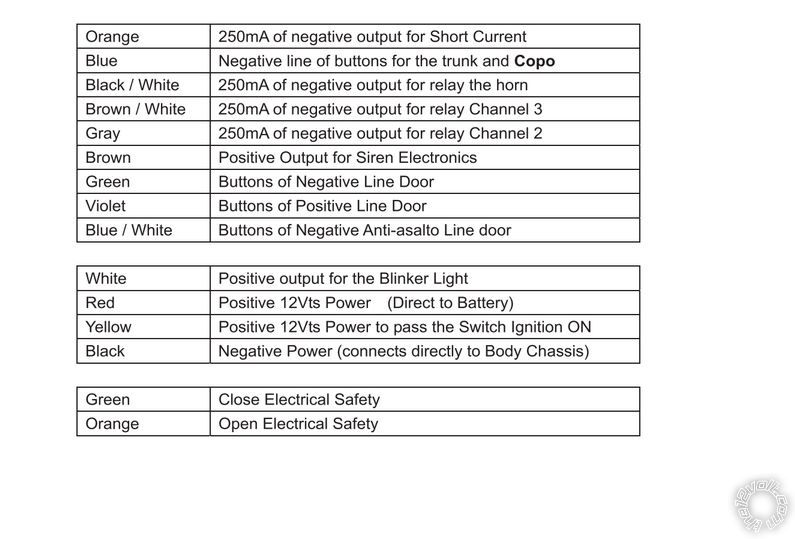
because the car has a negative door lock / unlock system and the kit i bought has a + and - wires to the lock unlock kit brain
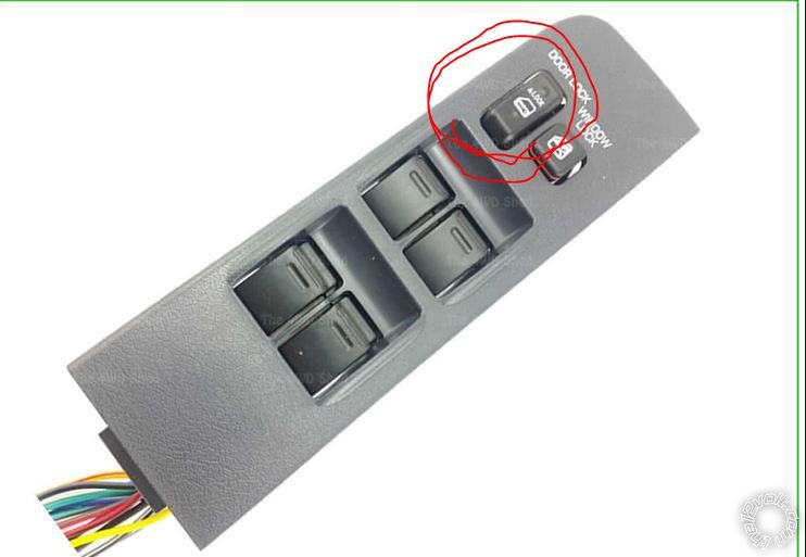
i tried to connect it to the armrest lock/unlock but it didn't work out
any one done that before or any help how wire it
thanks
kreg357 
Platinum - Posts: 7,802
Platinum spaceThis member has made a donation to the12volt.com. Click here for more info.spaceThis member has been recognized as an authority in Electrical Theory. Click here for more info.spaceThis member has been recognized as an authority in Mobile Security and Convenience. Click here for more info.spacespace
Joined: January 30, 2009
Location: Pennsylvania, United States
Posted: January 22, 2020 at 6:22 AM / IP Logged Link to Post Post Reply Quote kreg357
Here is some info on the U.S. version Landcruiser of 1991 through 1997 from Bulldog Security :
POWER LOCK      BLUE/BLACK (TYPE B)       IN DRIVERS DOOR HARNESS
POWER UNLOCK    BLUE/YELLOW and BLUE/ORANGE (TYPE B)     IN DRIVERS DOOR HARNESS
Don't have any info on your RKE system but you should set it for (-) Door Lock and Unlock outputs.
A direct connection to the Lock wire is all you need. For the Unlock you will need two 1N4001 diodes
and follow this diagram :
http://diagrams.marktoonen.nl/DOWNLOADS/26500_LAND-CRUISER_TOYOTA%20UNLOCK%20DIAGRAM.pdf
To locate and test the above mentioned lock wires use a Digital Multi Meter set to 20V DC. Connect the Red test lead
to +12V constant and the Black test lead to the suspect wire. Press the drivers door lock/inlock buttons to see the DMM
go to +12V.
Soldering is fun!
secur60 
Member - Posts: 4
Member spacespace
Joined: January 16, 2020
Location: Australia
Posted: January 22, 2020 at 6:56 AM / IP Logged Link to Post Post Reply Quote secur60
thanks mate for your reply really appreciated
i forgot to write some info about the car and the system
its RHD Australian model without factory alarm or key less system
i searched online a lot almost all what i found was for U.S cars
all the wires were different color/location etc
i located the lock/unlock wires as you said using the multi meter when i tried to connect them nothing happened but i didn't used any diodes it was a little bit confusing because some people worked out for them with direct connection to lock/unlock wires some got lucky with the wires before the central door control unit , but i had no luck anyway
last try was to connect the wires to the main lock/unlock switch i hacked the rear cover the button has 3 wires 3.2.1 if i want to lock it 1 and 2 will contact so the car locks to unlock it 2 and 3 will connect to each other so it opens , there were my problem what to do about the 3rd wire or how to connect it , some people worked out for them with direct connection to lock/unlock wires some got lucky with the wires before the central door control unit , but i had no luck anyway
1994 80 Series Landcruiser Keyless Wiring -- posted image.
kreg357 
Platinum - Posts: 7,802
Platinum spaceThis member has made a donation to the12volt.com. Click here for more info.spaceThis member has been recognized as an authority in Electrical Theory. Click here for more info.spaceThis member has been recognized as an authority in Mobile Security and Convenience. Click here for more info.spacespace
Joined: January 30, 2009
Location: Pennsylvania, United States
Posted: January 22, 2020 at 9:01 AM / IP Logged Link to Post Post Reply Quote kreg357
It might be easier to use relays controlled by the aftermarket RKE system to duplicate what the central locking switch does.
You would need two 30/40 Amp SPDT relays and the 5 wire harness.
Lock Relay :
Relay Pin 85 to RKE (-) Lock output
Relay Pin 86 to +12V constant
Relay Pin 30 to central locking switch Pin 2
Relay Pin 87 to central locking switch Pin 1
Unlock Relay :
Relay Pin 85 to RKE (-) Unlock output
Relay Pin 86 to +12V constant
Relay Pin 30 to central locking switch Pin 2
Relay Pin 87 to central locking switch Pin 3
All that is left is to figure out which two wires from the RKE system supply a (-) output with the remotes lock/unlock commands.
Soldering is fun!

If you wish to post a reply to this topic, you must first login.
If you are not already registered, you must first register.

  Printable version Printable version Post ReplyPost New Topic
You cannot post new topics in this forum
You cannot reply to topics in this forum
You cannot delete your posts in this forum
You cannot edit your posts in this forum
You cannot create polls in this forum
You cannot vote in polls in this forum

  •  
Search the12volt.com
Follow the12volt.com Follow the12volt.com on Facebook
Thursday, October 31, 2024 • Copyright © 1999-2024 the12volt.com, All Rights Reserved Privacy Policy & Use of Cookies
Disclaimer: *All information on this site ( the12volt.com ) is provided "as is" without any warranty of any kind, either expressed or implied, including but not limited to fitness for a particular use. Any user assumes the entire risk as to the accuracy and use of this information. Please verify all wire colors and diagrams before applying any information.

Secured by Sectigo
the12volt.com spacer
Support the12volt.com
Top
the12volt.com spacer