the12volt.com spacer
icon

momentary p/b start and stop 1st post


Post ReplyPost New Topic
< Prev Topic Next Topic >
miniboy 
Member - Posts: 10
Member spacespace
Joined: September 07, 2009
Posted: September 07, 2009 at 10:07 PM / IP Logged  

OK I am new to this site and only have enough electrical knowledge to make me dangerous! I have searched the forum for the answer to this question and have come close but could not find the solution.

Here is what needs to be done. 

1 momentary grounding switch that starts the car and turns it off

- 1st push and hold, ingition is turned on and starter engages until you let go of the button

-2nd push of the same button turns the car off.

No key will be used, power to the car will be controlled with a main latching solenoid in the trunk that is activated and deactivated with the alarm pad.

This system is available for around $130 from a comapny called Watson street works, but I was intersted in doing it myself and hopefully for a little cheaper. I called them and they told me that the system was made up of a bank of latching relays but did not tell me how it works or was wired exactly. (this does not suprise me)  

Here is a link to the system:  http://www.watsons-streetworks.com/ignition_switches.html

Can anyone help with the wiring of the relays for this application.

Thanks

i am an idiot 
Platinum - Posts: 13,710
Platinum spaceThis member consistently provides reliable informationspace
Joined: September 21, 2006
Location: Louisiana, United States
Posted: September 08, 2009 at 4:08 AM / IP Logged  

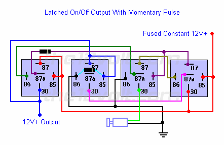
You will need the following relay setup to turn the igniion on and then back off.  This will be performed by the single momentary button.

You will need an additional relay with a resistor/capacitor delay circuit.  The delay circuit will keep the relay from energizing for the first half of a second of the initial push of the button. 

The only thing that I am unsure of is if the latching relay setup below will chatter during an extended turn on pulse.  I will find the diagram for the delay relay this evening.

Latched On/Off Output Using a Single Momentary Pulse ( link)
Similar to the momentary to constant configuration above, we can engage and disengage the latched output with a single pulse from a switch or an output from an alarm or remote keyless entry. The first pulse from the switch will engage the latch. The next pulse from the switch will disengage the latch.
 
momentary p/b start and stop 1st post -- posted image.

miniboy 
Member - Posts: 10
Member spacespace
Joined: September 07, 2009
Posted: September 08, 2009 at 6:05 PM / IP Logged  

Thanks, I will check back for that diagram. Can you tell me is there any way to delay the starter relay any more than half a second? I do not mind having to hold the button down for a full second or two.

Also can you tell me the specifics on the items below circled in red. I assume they are diodes but are they as certain size and where would I purchase them...............Like I said - just enough knowledge to be dangerous!

momentary p/b start and stop 1st post -- posted image.
miniboy 
Member - Posts: 10
Member spacespace
Joined: September 07, 2009
Posted: September 08, 2009 at 6:06 PM / IP Logged  
Oops...Not sure what happened there!
i am an idiot 
Platinum - Posts: 13,710
Platinum spaceThis member consistently provides reliable informationspace
Joined: September 21, 2006
Location: Louisiana, United States
Posted: September 08, 2009 at 6:29 PM / IP Logged  
If you are talking about the components mounted to the 2 left relays, yes they are diodes. They are rated at 1 amp.  Radio Shack sells them.  They are 1N4001 or any number greater than the 1 at the end.
borischan 
Member - Posts: 5
Member spacespace
Joined: February 26, 2010
Posted: March 11, 2010 at 3:42 AM / IP Logged  
i am an idiot wrote:

You will need the following relay setup to turn the igniion on and then back off.  This will be performed by the single momentary button.

You will need an additional relay with a resistor/capacitor delay circuit.  The delay circuit will keep the relay from energizing for the first half of a second of the initial push of the button. 

The only thing that I am unsure of is if the latching relay setup below will chatter during an extended turn on pulse.  I will find the diagram for the delay relay this evening.

Hi guys, I thought I'd bump this thread instead of making a new one.
I am also making a car push button start set up, and I have used the momentary latching circuit found on here. Actually I used the 5 relay set up, no diodes lying around.
Anyway as mentioned above, using a normal push button switch I get chattering, easy to get the circuit to latch, possible but difficult to get it to unlatch, unless I develope lightning speed fingers!!
Any ideas on solving this problem?
Thanks
KPierson 
Platinum - Posts: 3,527
Platinum spaceThis member consistently provides reliable informationspace
Joined: April 14, 2005
Location: Ohio, United States
Posted: March 11, 2010 at 8:55 AM / IP Logged  

Using a lataching relay as pictured for ignition is EXTREMELY dangerous.

Latched relays will not  stay latched if they exposed to a sudden shock.  If you are going to use relays you need a controller that keeps constant voltage on the relays.  Otherwise, if you hit a big bump there is a good chance your car will shut off.

The reason for this is simple and is based on the principle of how relays work.  When you latch one relay with either itself or another relay the only thing hold the relay in is the fact that current is still flowing through the contacts.  The only thing "holding" the contacts together is a small magnetic field.  If the relay is exposed to a shock that is greater then the magnetic field the contacts will start to seperate.  As soon as the current breaks the magnetic field will collapse and the entire circuit will drop out until it's relatched.

There is a # video I made about this a while back that shows how little force is needed on a relay to break the latch.

Now, if you have a controller of some sort that is constantly outputting voltage to the coil even if you hit a bump the current may stop flowing but will come right back on because the magnetic field won't be interuppted.  The "bouncing" of the contacts happens at a mS level and most likely wouldn't be noticed to the driver (or the car).

If you are stuck with using only relays try to find a real mechanical latching relay instead of one that uses magnetic energy for the latch. 

Kevin Pierson
borischan 
Member - Posts: 5
Member spacespace
Joined: February 26, 2010
Posted: March 12, 2010 at 2:50 AM / IP Logged  
Thanks for that info, very interesting. Actually I looked for a mechanical latching relay that would latch and unlatch from the same push button switch, but couldn't find one. That's when I found the latching circuit here. I'll look into this further.
Anyway, this project is still on my desk, and back to my last question, how can I get a pulse from my single momentary button?
Just using the button itself is not good enough.
miniboy 
Member - Posts: 10
Member spacespace
Joined: September 07, 2009
Posted: March 12, 2010 at 2:03 PM / IP Logged  
I have installed this set up in my 1964 Mini with a Honda engine. This is a pretty bumpy car and I have not had a problem with it yet. I added an additional relay for the accessory items in the car.  So far so good, we will see!
miniboy 
Member - Posts: 10
Member spacespace
Joined: September 07, 2009
Posted: March 12, 2010 at 2:05 PM / IP Logged  
I also have not noticed any chattering on my setup. When would that occur so I can listen for it? Startup or shutdown?
Page of 3

  Printable version Printable version Post ReplyPost New Topic
You cannot post new topics in this forum
You cannot reply to topics in this forum
You cannot delete your posts in this forum
You cannot edit your posts in this forum
You cannot create polls in this forum
You cannot vote in polls in this forum

  •  
Search the12volt.com
Follow the12volt.com Follow the12volt.com on Facebook
Sunday, May 18, 2025 • Copyright © 1999-2025 the12volt.com, All Rights Reserved Privacy Policy & Use of Cookies
Disclaimer: *All information on this site ( the12volt.com ) is provided "as is" without any warranty of any kind, either expressed or implied, including but not limited to fitness for a particular use. Any user assumes the entire risk as to the accuracy and use of this information. Please verify all wire colors and diagrams before applying any information.

Secured by Sectigo
the12volt.com spacer
Support the12volt.com
Top
the12volt.com spacer