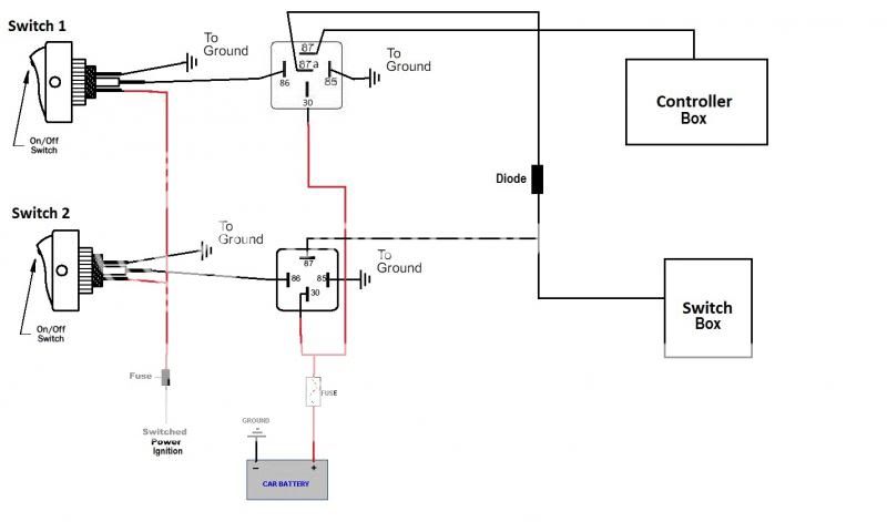
That diagram is fine, though the diode can be omitted. (Series didoes are used to isolate different signals or different power sources. But since your power sources are the same (#30), it doesn't matter if the relays #87 & #87a cross-connect them. It's the same if the switches are used instead of the relays (assuming a lit switch's light is from
#87 which is what you'd want).
Both solenoids (valves) need to be grounded. They need +12V on one end to actuate, but the other end must be grounded to "return" the current.
FYI - electricity can only flow in a loop, eg battery+ thru the load (light, solenoid, resistor) out thru the -ve end (or GND) back into the battery-. Break that circuit and current flow stops.
The eBay #110881515304 is 12V and hopefully you've chosen the DC12V version of the 400 Series.
Current wise, the 4v410-15 solenoid is 4.8W hence (from P=IV => I=V/P) 4.8W/12V = 0.4A - let's assume
0.5A and allow/design for 1A.
I can't see any power or current rating for eBay 110881515304, but it's probably similar.
Hence 12V switches with contact ratings of 1A or should be fine.
The switches you linked are 20A rated to they are well overrated. (That's not an electrical problem, maybe just cost & size.)
But omitting the relays means that the Switched Power Ignition (IGN) needs to carry the full solenoid load instead of the 500mA (max) of the relay coils.
But those solenoids seem to be low current - ie, 500mA & ?? - maybe 1A or 2A total, and that's not a big difference, and it can probably be taken from an existing fused IGN circuit. (Choose one that isn't critical, else is "logically matched" to what you are doing - ie, if this solenoid fuse blows, it doesn't matter if the fuel pump or engine or brake lights or flashers (whatever is chosen) also stops working. But beware solenoid spikes - more on that later.)
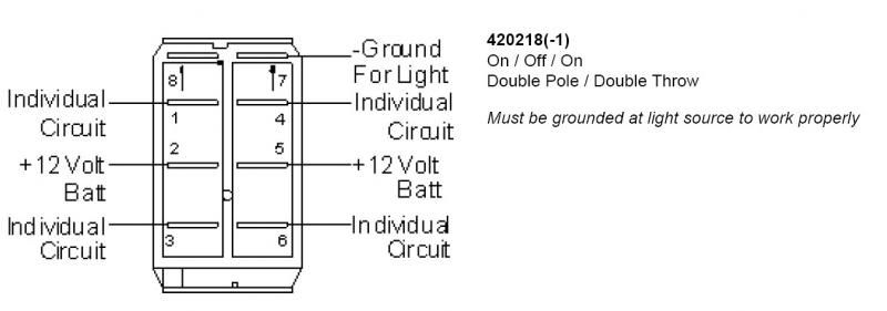
Re the switches, they are center-off (3 position) and you may prefer 2 position. And they are DPDT but maybe the 2nd pole is used for the lamp?
If the
top changeover switch is centre-off, you must switch it to either
end. If you leave it in the middle, the controller (and the valve [switch box]) will be off.
But there should be 2-position equivalents available.
And you can omit the relays since an SPDT switch does the switching you require. (IE - SPDT aka 2-way aka change-over; of say 1A or higher rating)
And the on-off switch is merely an SPDT with the unused "throw" (position) left unconnected.
But for SPDT lit switches, you want to be able to select which of the outputs light the indicator (since you'd want the 2-way unlit in its [/]normal to controller box position (ie, when in the
off position).
And like anything electrical (ie, the
loop), the switch lamps/s must have their own GND (as shown in your diagrams).
But
never confuse the lamp GND terminal with other terminals. If it's a common lit on-off (SPST) switch with 3 terminals, the GND will be at one end with the +12V supply at the
opposite end, and the switched load from the
center terminal. Any other combination and you'll connect or switch the +12V input direct to GND, and that's called a short. (And without proper fusing, that's called smoke & fire & expense etc!)
Some switches could have different arrangements so be careful. (And yes, I think many of us have made mistakes on lit switches!)
More FYI:
Those switches are fine other than being 3 position, though if you can think of something else you want that is independent of those solenoids, they may be handy.
But I usually won't use switches that big - unless I want a BIG switch for physical reasons (looks, gloves, etc).
That's for various reasons...
Electrically, if I need to switch "big" currents, I prefer a relay. In part that's because I don't like switches (even 20A) carrying more than a few Amps. Hence I'll add relays. (Relays tend to last, switches tend to fail.)
It also means I can use smaller (and cheaper) switches that only need to switch typical 60mA to 250mA relay coils - ie, 0.5A or preferably 1A rated switch contacts. And there are many more switches to chose from.
It also means thinner wiring to the switch - ie, in the cabin etc. The relays can be anywhere with their minimal heavy wiring to the loads, and for things like headlights etc, as short as practicable (ie, the relay is between the battery and light; the heavy light wire does not have to go into the cabin etc).
In your case however, the loads are small so it's not a big issue. If those switches are what you want, use them. (Relays could be added, but IMO that's adding more complication unless fusing is an issue...)
Re "spikes". Breaking current to relay coils and solenoids causes a reactive voltage spike (like an ignition coil). That can damage sensitive components/electronics.
Now, all vehicle loads
should have their own spike +12V & GND supply resilience (not necessarily for their inputs & outputs though).
But it may be pertinent to add a quenching aka spike-suppressing diode across each solenoid, especially if tapping in to an existing fused IGN circuit. (As many say, it's cheap insurance. Besides, it certainly helps keep the electrics clean from spikes & noise etc.)
That's easy - a diode across each coil/solenoid with the band or line end towards the
+ve terminal/wire; the other end to GND.
For coils/solenoids up to 0.5A, 1N4004 or 1N4007 diodes are fine.
For coils/solenoids up to 1.5A, 1N5404 or 1N5408 diodes are required.
(For both above IN400x & 1N540x, and last number of 4 and above is fine. The numbers I've given tend to be the common versions available.)
BTW - such quenching diodes are often places across relay coils. (Relay coils are "solenoids" - ie, wound loops of wire - but let's not go there for now!)
Geez, that became a ramble and a half - way too much for a "simple" job like this LOL!
But it includes my usual FYIs and extra bits in an attempt to enable you to reach your final "perfect" solution. Hence all the options...
Ignore the irrelevant or confusing bits, or focus on one or a few and reread the others later. It is confusing at first but eventually all comes together... (And then you realise how simple it all is, but just how many considerations (spikes, switch lamps) and options (relays?, separate fused circuits?) are available!)
Not that I tackled fusing in depth, but if tapping into and existing fuse you won't need to add one. However all your wiring should have a current rating equal to or higher than that fuses' rating (eg, 10A or 15A etc). Otherwise insert an additional smaller fuse before your smaller wiring.
I hope that all makes sense. AND that I haven't made an error or missed something...!


 Any help, input, suggestions, bitches, or complaints are welcomed.
I am a visual person, so diagrams are helpful.
Thanks again.
Any help, input, suggestions, bitches, or complaints are welcomed.
I am a visual person, so diagrams are helpful.
Thanks again.

 Thanks again.
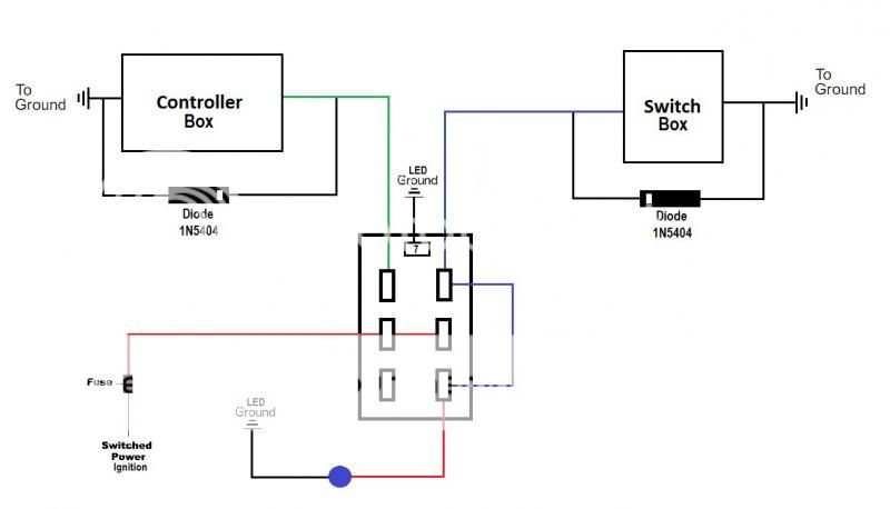 And The schematic for the switch I ordered:
 I understand concepts, but the specifics are cloudy.
 How obvious... Damned
  That diagram is spot on. You even have the quenching diodes the correct way.
I may as well disappear for a week or two.
Re diodes, see the links at the top of the page, eg
That diagram is spot on. You even have the quenching diodes the correct way.
I may as well disappear for a week or two.
Re diodes, see the links at the top of the page, eg  Printable version


