the12volt.com spacer
icon

backup cam wiring diagram


Post ReplyPost New Topic
< Prev Topic Next Topic >
silentnoise713 
Member - Posts: 5
Member spacespace
Joined: March 13, 2013
Location: Pennsylvania, United States
Posted: March 13, 2013 at 4:19 PM / IP Logged  

Hello All,

Let me start by saying I’m a newbie here.  I’m also not nearly as technical as most of the posters here so please bear with me if I’m totally off.   I sometime wish I stuck it out with EE instead of changing to IT.

I am looking to add a rear view mirror with 4.3” LCD and a backup camera to my Mazda5.  The idea is to use a Dual SPST relay to power up both the mirror and camera when the transmission is in reverse.  I don’t want either the mirror or camera to be on all the time (later to add an override switch to kill it all together).  I’ve planned out my wiring schematics as below and wanted your input if I may have missed something.   Does everything look ok?  Btw, I choose to use a Dual make SPST relay thanks to the explanation from this awesome site!

backup cam wiring diagram -- posted image.

Once I get confirmation on this, I will update this with a version 2 where I add an On-Off-On 3-way toggle switch to intercept the coil signal from the transmission.  More to come… :)

Thanks!

silentnoise713 
Member - Posts: 5
Member spacespace
Joined: March 13, 2013
Location: Pennsylvania, United States
Posted: March 13, 2013 at 5:58 PM / IP Logged  
Sorry, I think this is in the wrong section. Can a mod move this to the correct sub-forum?
oldspark 
Gold - Posts: 4,913
Gold spacespace
Joined: November 03, 2008
Location: Australia
Posted: March 13, 2013 at 6:21 PM / IP Logged  
Insert a fuse near the battery+.
Add a protection diode across 85 & 86 (band towards 86) in case the R also feeds other sensitive circuits.
The diagram assumes R is supplying +12V when in Reverse.
You don't need a dual SPST relay. A 2-terminal output SPST will do, else a junction on a typical SPST relay (ie, a female to 2 male spade joiner/junction).
howie ll 
Pot Metal - Posts: 16,466
Pot Metal spacespace
Joined: January 09, 2007
Location: United Kingdom
Posted: March 14, 2013 at 1:31 AM / IP Logged  
I don't see you'd need a relay, unless the screen uses more than about 5 amps.
silentnoise713 
Member - Posts: 5
Member spacespace
Joined: March 13, 2013
Location: Pennsylvania, United States
Posted: March 14, 2013 at 11:47 AM / IP Logged  

oldspark wrote:
Insert a fuse near the battery+.
Doh!  How did I forget that!  Just to clarify, this is not going to the battery directly, rather the +12V feed and a fuse will be added.
[QUOTE] Add a protection diode across 85 & 86 (band towards 86) in case the R also feeds other sensitive circuits.

The diagram assumes R is supplying +12V when in Reverse. [/QUOTE] 

Can you point me to a specific suggested diode (RadioShack)?  I'm actually tapping into to the Reverse signal feed, which I understand is 12V.  I need to confirm if this goes to the BCM. If not, do I still need the diode?
[QUOTE]
You don't need a dual SPST relay. A 2-terminal output SPST will do, else a junction on a typical SPST relay (ie, a female to 2 male spade joiner/junction). [/QUOTE] I'm not familiar with all the different types of relays.  What exactly is a 2 terminal output SPST vs a dual make SPST?  Can you point me to a source to clarify?  I though about just using a single SPST and adding a junction to "split" the power source but I depending on how I plan out part 2, this may be a conflict.  


Thanks for the feedback!

silentnoise713 
Member - Posts: 5
Member spacespace
Joined: March 13, 2013
Location: Pennsylvania, United States
Posted: March 14, 2013 at 11:55 AM / IP Logged  

howie ll wrote:
I don't see you'd need a relay, unless the screen uses more than about 5 amps.

What other options do you have in mind?  Are you leading to powering both off the reverse light or something else?  For part 2, I'd like to add additional in cabin cam and maybe front cam.  I also want to be able to manually keep it OFF b/c I only want it on in situations when I need it, not ever time the gear passes through Reverse –fearing surge and constant power cycles.  My understanding (could be wrong) is that the transmission signal has a slight (1sec) delay to avoid this. 

Open to any suggestions.  

howie ll 
Pot Metal - Posts: 16,466
Pot Metal spacespace
Joined: January 09, 2007
Location: United Kingdom
Posted: March 14, 2013 at 3:10 PM / IP Logged  
Yes your points are right but you would only need a relay for extra screens, the cameras are using very little juice.
Nought wrong with switches, 1 second delay would make no real difference.
The usual amateur problem, over thinking and over complicated, usually = more chances to fail.
KISS.
oldspark 
Gold - Posts: 4,913
Gold spacespace
Joined: November 03, 2008
Location: Australia
Posted: March 14, 2013 at 8:01 PM / IP Logged  
The [QUOTE] needs to include the "=userID" (or other word/s??) - eg QUOTE=silentnoise713.
Relays:
Generally only needed if the existing +12V switch or output cannot handle the extra current of the camera. But as Howard said, cameras are usually low current (under 1A) unless perhaps with extra lighting, but even then IR or white LEDs may not add much.
Relays are also used if you need isolation or independence from the source (switch etc) - eg, if the switch switches 9V or 5V or GND and you need 12V for the load (camera).
And they are used if you want a different power source - eg, cleaner +12V from the battery rather than the noisier or lower voltage IGN or ACC or reverse-switch's +12V.
Types of relays:
I guess you know of the Relays link up the top of this page? That's a good reference. In fact it just taught me what "dual make" referred to (LOL).
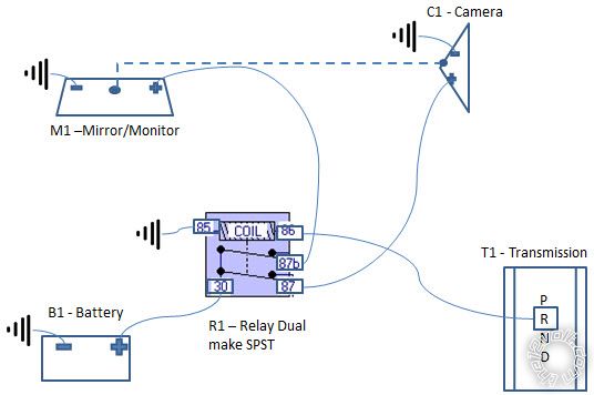
Your diagram had 87 & 87b as its contacts which is a "dual output" 87. The dual output terminals might simply be 2 terminals joined internally to the same contact, or each to its own contact as per the dual make depicted in your diagram.    
Electrically a dual-make relay with 2 internal arms (from the same terminal 30) and separate output terminals 87 & 87b is the same as a single-arm with 2 output terminals which is the same as a common on-off SPST relay with an external 2-wire join from 87.
So why use a 2-armed or i]dual-make independent output relay? When the supplied circuits are not supposed to be connected together when the relay is off. EG - fuel injector +12V to ECU +12V etc. Isolating diodes could be used instead, but that means a voltage drop of ~0.6V to the loads. Also loads like injectors can take several Amps which mean a big diode and lots of heat.
Anyhow, SPST translates as a common on-off relay, commonly referred to as a 4 pin (relay).
Its contacts are 30 & 87. 87 is aka the NO = Normally Open contact - ie, it closes and connects to 30 when the relay is energised (12V across coil 86 & 85; by convention +ve to 86 & the more -ve to 85).
The other common type is the SPDT - still a Single Pole, but Double Throw meaning it has an extra NC (Normally Closed) contact which is connected to 30 when the relay is de-energised (ie, its "Normal" state when on the shelf or unpowered).
SPDTs are also called changeover (switches or) relays, and sometimes "5-pin" though I dislike that term because f.ex a dual-make SPST also has 5 pins.
But look for the relay schematic drawn on most relays. I always used them and NEVER used the DIN numbering 85, 86, 30, 87, 87a etc. (That only started after I joined the12volt! And it will be fun seeing what happens with the newer "micro" relays that use 1, 2, 3, 4, 5 instead!)
In part that is because some dual-output relays may use 87 & 87b instead of 87 & 87. (I even have a Hansa dual-output SPST where the 2nd terminal is labelled 87a which is totally incorrect!! That could lead to disaster if 87 is to +12V and 87a is to GND which is common for some circuits - eg, fans and motors)
Also technically "30" is defined as "+ from the battery direct". So what if we want to switch IGN or GND - do we need a relay with 15 or 31(abcd) instead or 30? No - it's just a contact/terminal. 87 & 87a can be the "inputs" (say +12V battery and IGN +12V) and 30 can be the output (eg radio +12V).
Sorry, I do get carried away...
Protection diode:
In short, 1N4004 or 1N4007 (whichever available or cheaper; maybe the 007 if priced the same).
But for a bit more info (here I go again!)...
The reverse biased diode across the relay coil protection aka spike protection or snubber or quenching diodes are typically 1N4004 or 1N4007 diodes. They are often also used as isolation diodes (ie, in series with input or output wires as opposed to parallel across a relay coil).
The 1N400x series handle up to 1A of current, and that's enough to "snub" the spike from a relay coil rated up to ~500mA.
The last x digit refers to their (reverse) voltage rating, aka PIV, Peak Inverse Voltage.
The lowest was the 1N4001 (50V) which is fine for series isolation in vehicles, but coils can spike typically around 200V, so the 1N4004 with 400V PIV is used, else the 1N4007 with 1kV PIV.
These days you tend to only find the 1N4004 or 1N4007, the others having been dropped from production. I suspect one day only the 1N4007 will be available - it does all the others do but tolerates 1,000V, and since they are all the same size and manufacturing process...
You may as well get a pack else several 1N4004s or 007s as they are a common diode and used in many applications - ie, protection and interconnect isolation up to 1A. (The 1N540x series handles 3A, but they are fatter and less convenient.)
Individually 1N400x are usually ~$0.25c each, but can be ~5c each in packs of 20 or 100 etc.   
Sorry if all the extra guff is confusing, but I suspect you'll appreciate some demystification and the extra info/tips.
Luckily being non-verbal I suspect at least your silentnoise is happy. backup cam wiring diagram -- posted image.
howie ll 
Pot Metal - Posts: 16,466
Pot Metal spacespace
Joined: January 09, 2007
Location: United Kingdom
Posted: March 14, 2013 at 8:10 PM / IP Logged  
Er Peter, wouldn't it have been easier to refer the OP back to my thread on "Relay Info"?
oldspark 
Gold - Posts: 4,913
Gold spacespace
Joined: November 03, 2008
Location: Australia
Posted: March 14, 2013 at 8:58 PM / IP Logged  
Hey silentnoise713, I should have mentioned Howard's great relays; general info OP.
Sorry, it's that old in OLDspark again. (And no proper brekky, just a cold coffee from yesterday.)
Oh Howard - sorry, I missed your last reply... Otherwise I'd say THANKS!! And a very BIG thanks at that.
Page of 2

  Printable version Printable version Post ReplyPost New Topic
You cannot post new topics in this forum
You cannot reply to topics in this forum
You cannot delete your posts in this forum
You cannot edit your posts in this forum
You cannot create polls in this forum
You cannot vote in polls in this forum

  •  
Search the12volt.com
Follow the12volt.com Follow the12volt.com on Facebook
Friday, June 14, 2024 • Copyright © 1999-2024 the12volt.com, All Rights Reserved Privacy Policy & Use of Cookies
Disclaimer: *All information on this site ( the12volt.com ) is provided "as is" without any warranty of any kind, either expressed or implied, including but not limited to fitness for a particular use. Any user assumes the entire risk as to the accuracy and use of this information. Please verify all wire colors and diagrams before applying any information.

Secured by Sectigo
the12volt.com spacer
Support the12volt.com
Top
the12volt.com spacer