the12volt.com spacer
icon

fuel gauge and sending unit


Post ReplyPost New Topic
< Prev Topic Next Topic >
cahilj 
Member - Posts: 11
Member spacespace
Joined: February 21, 2008
Posted: March 17, 2012 at 12:22 PM / IP Logged  
I'm reaching out here. I've asked this same question on several forums now, and no one can seem to give me an answer.
I have a fuel level sending unit that is 12v. It provides a 0-5v output for the gauge (0 empty, 5 full). I would like to use it with a gauge that has the typical GM input of 0-90 Ohm (0empty, 90 full) at 12v.
I've spent hours searching, but I can't seem to find anyone who has done this, and I'm not even sure it's possible. I found one (yes, only one) guy who did something similar in a battery powered Porsche. The Porsche gauge is 0-75 Ohm input. Link to site- http://cruzware.com/peter/blog/?cat=6. It's about 1/3 the way down, you'll see this-
fuel gauge and sending unit -- posted image.
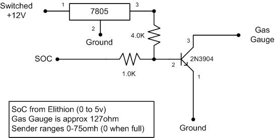
My knowledge of circuits like this isn't enough to be able to know if this would work or not. I realize the values would probably need to be changed. Can someone tell me if I'm at least headed in the right direction? And if I am, how do I go about getting the right values? Thanks.
KPierson 
Platinum - Posts: 3,527
Platinum spaceThis member consistently provides reliable informationspace
Joined: April 14, 2005
Location: Ohio, United States
Posted: March 17, 2012 at 7:26 PM / IP Logged  
Your transistor is a discreet device - not resistive. With the way your circuit is set up when SOC is 0 you will have only 1vdc going in to the base of the transistor which should be enough to turn it on at which point it will output a straight ground to your gauge. As your SOC voltage drops your base voltage will drop and eventually the transistor will just shut off and not pass current at all.
Kevin Pierson
cahilj 
Member - Posts: 11
Member spacespace
Joined: February 21, 2008
Posted: March 18, 2012 at 4:16 PM / IP Logged  
So... you're saying this won't work? Like I said, I don't know a whole lot about these types of things, just the basics. This is just a diagram I found online. Do you have any idea what it should look like to work?
KPierson 
Platinum - Posts: 3,527
Platinum spaceThis member consistently provides reliable informationspace
Joined: April 14, 2005
Location: Ohio, United States
Posted: March 19, 2012 at 5:38 AM / IP Logged  
To make it would you need to replicate the output of the correct sending unit - meaning you need a varying resistance on the output. They make "digital" potentiometers - perhaps that would work? Will be much more difficult though then a simple transistor.
Kevin Pierson
oldspark 
Gold - Posts: 4,913
Gold spacespace
Joined: November 03, 2008
Location: Australia
Posted: March 19, 2012 at 12:37 PM / IP Logged  
It's called a transconductance amplifier - ie, voltage to resistance.
FETs can be used. Chips were common too - eg LM13700, but that may need a split supply (ie, +/- 5V etc).
If it is for a normal fuel gauge, I'd suggest getting the original sender.
If it's for a BCM, why not use an offset or expanded-scale gauge instead (eg a series zener diode)? But that assumes the BCM merely uses voltage for a battery-capacity or SOC.
If it's a "true capacity" BCM, then stick to its 0-5V output.
The GM gauge should be able to be modified to sense 0-5V, though it may be a high-current meter which the 0-5V BCM output cannot drive (hence need a voltage-follower).
All meters are ammeters and use resistors to convert ranges or convert voltages to current.
cahilj 
Member - Posts: 11
Member spacespace
Joined: February 21, 2008
Posted: March 21, 2012 at 11:12 AM / IP Logged  
I spent some more time searching and found the transconductance amplifier. I was going to ask if it would be able to work.
I can't go back to the original sending unit. It is a swing arm type, and I now have a fuel cell with foam, so I had to switch to a capacitive tube type sender.
I would like to keep the factory gauge in the dash, but I am not opposed to converting it to work with a voltage input.
Is it possible to isolate the gauge circuit from the rest of the dash, then use only the sender to drive it? If I can find out the draw of the gauge? Or am I way off base?
oldspark 
Gold - Posts: 4,913
Gold spacespace
Joined: November 03, 2008
Location: Australia
Posted: March 21, 2012 at 11:44 AM / IP Logged  
Capacitive senders are usually voltage output - I presume hence your 0-5V.
Transconductance should work, it's a matter of finding he right conversion (circuit), ie, 0-5V to 5-90 Ohm or 90-5 Ohms etc.
cahilj 
Member - Posts: 11
Member spacespace
Joined: February 21, 2008
Posted: April 03, 2012 at 8:56 PM / IP Logged  
Well, I was able to find a company that will make me a custom ordered sender with the 0/90Ohm range. And at a reasonable price. This will save me headache and testing, and provide a warranty.
Thanks for everyone's help!

Sorry, you can NOT post a reply.
This topic is closed.

  Printable version Printable version Post ReplyPost New Topic
You cannot post new topics in this forum
You cannot reply to topics in this forum
You cannot delete your posts in this forum
You cannot edit your posts in this forum
You cannot create polls in this forum
You cannot vote in polls in this forum

  •  
Search the12volt.com
Follow the12volt.com Follow the12volt.com on Facebook
Saturday, April 27, 2024 • Copyright © 1999-2024 the12volt.com, All Rights Reserved Privacy Policy & Use of Cookies
Disclaimer: *All information on this site ( the12volt.com ) is provided "as is" without any warranty of any kind, either expressed or implied, including but not limited to fitness for a particular use. Any user assumes the entire risk as to the accuracy and use of this information. Please verify all wire colors and diagrams before applying any information.

Secured by Sectigo
the12volt.com spacer
Support the12volt.com
Top
the12volt.com spacer