the12volt.com spacer
icon

multiple switch and relay setup


Post ReplyPost New Topic
< Prev Topic Next Topic >
piracywebmaster 
Member - Posts: 11
Member spacespace
Joined: June 27, 2006
Location: United States
Posted: August 21, 2006 at 1:30 AM / IP Logged  

Ok, I am having major problems trying to figure out how to make a circuit work for me.

A little background, I'm setting up a C02 system in my car, and I have a steering wheel that has the 2 momentary switches on it, (F&F sucks, I'm not copying them!) well, for me to stay "Legal"  I need a switch (safety) on my dash, to switch between 2 things. I am working with a limited amount of space on the dash for switches, so I have to keep them down

Here's what needs to happen...

*When the Safety switch is off (open), I need the buttons on the steering wheel to sound the horn.

*When the Safety switch is on (closed), I need the buttons on the sterring wheel to go to 2 seperate items, one goes to my purge solenoid, and the other goes to the bottle solenoid. Each switch must go to a different item.

Pretty much when the safety switch is open, the S.W. buttons operate the horn, and when the safety switch is closed the S.W. buttons work my C02 purge solenoid, and the C02 bottle solenoid!

I doesn't matter how many relays I need to make this work, I've got plenty of space in the glovebox for relays, which is where most of mine has been relocated to.

I've been banging my head for almost a month trying to figure this out.

I think I included everything needed to know, just let me know!

geepherder 
Platinum - Posts: 3,668
Platinum spaceThis member consistently provides reliable informationspace
Joined: October 27, 2003
Posted: August 21, 2006 at 7:00 AM / IP Logged  

You didn't post the year/make/model of vehicle, so for simplicity's sake, let's assume your car has a negative trigger horn.  *Modify this as needed for your situation.*  You need 4 relays.  I suggest you don't power your safety switch with constant power, rather accessory or ignition.  This way you won't have to worry about killing your battery in the event you accidentally leave it switched.  Either that, or use a lighted switch and/or a warning buzzer to go off when the key is off with the door opened (more relays, etc.).  I'd prefer to just use accessory or ignition, though.  Okay, now here's what to do:

On both of your steering wheel buttons, ground one side.  (Remember that the steering column is not necesarily a good ground, so you may want to run/use a ground wire just to be safe.)  The remaining terminals on your buttons will each go to terminal 30 of their own relay.  Ground terminals 85 on both of these relays.  Terminals 86 will be powered by your safety switch.  Be sure to fuse wherever you connect for power.  Terminals 87 on both relays will supply a ground/negative trigger for the horn- connect to the factory negative trigger horn wire.  Use terminals 87a to control relays for either your purge solenoid or your bottle solenoid.

Good luck.

My ex once told me I have a perfect face for radio.
piracywebmaster 
Member - Posts: 11
Member spacespace
Joined: June 27, 2006
Location: United States
Posted: August 21, 2006 at 2:18 PM / IP Logged  

opps sorry, Its a 1990 nissan 240sx.

Thank you for th reply.

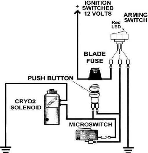
here is a wiring diagram for the bottle solenoid, I don't have one for the purge, but the purge is just hooked up into this circuit below.

multiple switch and relay setup -- posted image.

piracywebmaster 
Member - Posts: 11
Member spacespace
Joined: June 27, 2006
Location: United States
Posted: August 21, 2006 at 2:20 PM / IP Logged  
sorry, forgot to ask, where would I install the relay at on the circuit?
geepherder 
Platinum - Posts: 3,668
Platinum spaceThis member consistently provides reliable informationspace
Joined: October 27, 2003
Posted: August 21, 2006 at 8:23 PM / IP Logged  

Okay then, that helps.  To the left of the page, click vehicle wiring: https://www.the12volt.com/installbay/detail.asp?info=alarm&year=1989-90&make=Nissan&model=240%20SX&ID=18509&type=Alarm.  You can also check www.bulldogsecurity.com.  According to the link above, your horn wire is GREEN / WHITE (negative) at the steering column. 

One thing I forgot- depending on the current draw of your solenoids, you may not need the other relays.  If the current draw of your solenoids is within the safe limits of the push button switches on your steering wheel, the relays will not be necessary.  If you find this to be the case, simply wire a fused ignition power where the solenoid is grounded, and use the switch to supply the ground.  If you do need to use relays, simply wire terminals 30 and 87 in place of where the push button switch is.  Connect the same fused ignition power to terminal 86 on the new relay.  Terminal 85 on the new relay needs to be connected to terminal 87a of the first two relays in my above post. 

That should get you working.

My ex once told me I have a perfect face for radio.
piracywebmaster 
Member - Posts: 11
Member spacespace
Joined: June 27, 2006
Location: United States
Posted: August 22, 2006 at 12:08 AM / IP Logged  

so the first post you gave me has the correct info?

ok sounds good, took me awhile to figure it out, I forgot that I posted that image! LOL (been a long day, working on my 240sx)

ok, where you said wire a new relay into the push button, will the relay replace the switch? because that switch activates the solenoid to release the C02!

I'm sorry I'm not understanding the part about if I need the relays!

ok that image i posted was just for the bottle solenoid, there is another item, the purge solenoid, that has 2 wires, pos. and neg., where would I have to place the wires at on the second relay for the solenoids at?

geepherder 
Platinum - Posts: 3,668
Platinum spaceThis member consistently provides reliable informationspace
Joined: October 27, 2003
Posted: August 22, 2006 at 6:40 AM / IP Logged  

Yes, my first reply will allow you to operate the horn.

Yes, the new relay will replace the push button as it is in the above picture since the relay itself is a type of switch.  Then you'll just have to activate the relay using the push button as described above. 

If you're not sure if you need to use a relay, use one to be on the safe side and not burn up your momentary switches.  Since switches are rated for current, exceeding the rating can fry the switch.  The purpose of a relay is to alleviate that problem, since it only requires a small amount of current (around 150-200 mA through the energizing coil) to control a much larger current (up to around 30 A for a typical automotive relay) through the contacts.  It's important that you understand this, so if you need more information, click on relays to the left of this page under basics: https://www.the12volt.com/relays/relays.asp.  Also have a look on www.bcae1.com, and scroll down to relays.

I think once you understand this, the purge solenoid will make sense to you.  It should basically be the same as the above diagram without the microswitch.  You'll have the purge solenoid, a fused ignition power source, and the relay/switch will supply a ground (completing the circuit).

My ex once told me I have a perfect face for radio.
piracywebmaster 
Member - Posts: 11
Member spacespace
Joined: June 27, 2006
Location: United States
Posted: August 22, 2006 at 11:03 PM / IP Logged  

ok, thank you

i'm working on the wiring diagram right now, when I'm done, I'm going to scan it, and upload it to my website, and paste a link so you can check it out, to make sure I didn't miss anything or wire it wrong!

piracywebmaster 
Member - Posts: 11
Member spacespace
Joined: June 27, 2006
Location: United States
Posted: August 23, 2006 at 12:03 AM / IP Logged  
geepherder wrote:

If you do need to use relays, simply wire terminals 30 and 87 in place of where the push button switch is.  Connect the same fused ignition power to terminal 86 on the new relay.  Terminal 85 on the new relay needs to be connected to terminal 87a of the first two relays in my above post. 

That should get you working.

ok, sorry, while drawing up the schematic for this, I noticed on the solenoid relays, that 87a doesn't go anywhere. Can I ground them, or send them to a led so I know its off, or what?

I'll leave it alone until you get back to me on that.

Thanks Again for your continued help on this.

I went to Trade school, but we never did relays, we talked about them, but never worked with them. I was ticked off, because you always run in to something that has to use a relay!  :(

piracywebmaster 
Member - Posts: 11
Member spacespace
Joined: June 27, 2006
Location: United States
Posted: August 23, 2006 at 1:39 AM / IP Logged  

ok, I finished the schematic, would you be willing to look over it to make sure everything looks good? I would be very thankful if you would!!!

http://thepiracy.net/images/finished_safety_switch_setup.jpg  (mods if this is not acceptable, posting an image like this, please let me know!!! Thank You!)

on the bottom 2 relays for the solenoids, I left one connection incomplete, on both relays!

I'm not to sure about the bottom 2 relays anyways, see if they look like I wired them up correct, please.

Let me know if I messed up on any connections, you can pm me, and let me know that way also.

Thank You

John

Page of 2

  Printable version Printable version Post ReplyPost New Topic
You cannot post new topics in this forum
You cannot reply to topics in this forum
You cannot delete your posts in this forum
You cannot edit your posts in this forum
You cannot create polls in this forum
You cannot vote in polls in this forum

  •  
Search the12volt.com
Follow the12volt.com Follow the12volt.com on Facebook
Friday, May 3, 2024 • Copyright © 1999-2024 the12volt.com, All Rights Reserved Privacy Policy & Use of Cookies
Disclaimer: *All information on this site ( the12volt.com ) is provided "as is" without any warranty of any kind, either expressed or implied, including but not limited to fitness for a particular use. Any user assumes the entire risk as to the accuracy and use of this information. Please verify all wire colors and diagrams before applying any information.

Secured by Sectigo
the12volt.com spacer
Support the12volt.com
Top
the12volt.com spacer