the12volt.com spacer
icon

custom led strips?


Post ReplyPost New Topic
< Prev Topic Next Topic >
fragydig529 
Member - Posts: 3
Member spacespace
Joined: March 18, 2009
Location: Georgia, United States
Posted: March 18, 2009 at 3:12 AM / IP Logged  
To start, my car is an '01 Chevrolet Impala.
Well, I'm kinda a novice at car wiring, but I recently came into a ton of green LEDs, and green being my favorite color, I decided I would try to make my own LED strips to replace my current green neon kit in my car.
Got to thinking about it a bit, and for some reason, I'm confused. It's probably an easy answer, but for some reason I can't figure it out.
Here's the info on the LED
Reverse Current (uA) : <=30
Fv: 3.0v - 3.4v
Life Rating : 100,000 Hours
Max Power Dissipation : 80mw
Max Continuous Forward Current : 30mA
Max Peak Forward Current : 75mA
Reverse Voltage : 5~6V
I was reading alot about resistor this, resistor that. I came up with a few basic wiring diagrams.
custom led strips? -- posted image.
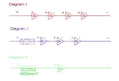
Now, I'm pretty sure all of these will work, not 100% sure on that. But the problem I was having was with paring these up... For some reason I can't figure it out. I want each strip to have 12 LEDs. Meaning that with Diagram 1, it'd take 3 "strips". Now do I need to wire each of the 3 strips to a common positive wire?
Like, how exactly could I get 12 LEDs on a strip in a series, without having 3 positive wires, and 3 negative wires? I'm sure I'm just being a moron. A diagram would be greatly appreciated. Thanks =D
i am an idiot 
Platinum - Posts: 13,674
Platinum spaceThis member consistently provides reliable informationspace
Joined: September 21, 2006
Location: Louisiana, United States
Posted: March 18, 2009 at 5:49 AM / IP Logged  
Diagram 2 or 3 will work fine.  Diagram 1 will fluctuate in brightness with alternator output.  And the LEDs will not be as reliable.
KPierson 
Platinum - Posts: 3,527
Platinum spaceThis member consistently provides reliable informationspace
Joined: April 14, 2005
Location: Ohio, United States
Posted: March 18, 2009 at 6:01 AM / IP Logged  

I personally would go with #3 - that way if you have a problem with one LED no other LEDs will be affected.  It will be a few more resistors, but in the long run it will most likely be worth it.

Your max forward current is 30mA and if you assume a max system voltage of 15 vdc your resistor value would be 500 ohms which would make it a 520 ohm resistor I believe.  470 ohms can result in an overcurrent situation and could shorten the life of the LEDs. 

Kevin Pierson
fragydig529 
Member - Posts: 3
Member spacespace
Joined: March 18, 2009
Location: Georgia, United States
Posted: March 18, 2009 at 12:14 PM / IP Logged  
Ok, so I'll go with the 500 Ohm resistor per LED setup. Does the wattage matter?
And to put my question up again.
How exactly can I wire these together into sets of 12?
I know it can't be
(+) --RESISTOR---LED---RESISTOR---LED---RESISTOR---LED---ETC-- (-)
Do I need to do something more like this
    - RESISTOR - LED - (-)
    |
(+) - RESISTOR - LED - (-)
    |
    - RESISTOR - LED - (-)
But to make a strip, that is going to take alot of wire.
So how would I go about putting these things onto a strip?
KPierson 
Platinum - Posts: 3,527
Platinum spaceThis member consistently provides reliable informationspace
Joined: April 14, 2005
Location: Ohio, United States
Posted: March 18, 2009 at 12:29 PM / IP Logged  
I would probably do it on a proto circuit board.  Solder the resistor and LEDs in to the board and then connect all the powers and ground on the bottom of the board with solder. 
Kevin Pierson
fragydig529 
Member - Posts: 3
Member spacespace
Joined: March 18, 2009
Location: Georgia, United States
Posted: March 18, 2009 at 12:36 PM / IP Logged  
Cool, will do. Thanks =D
It might be a week or so before I actually get around to doing this.
But I'll try to post pictures when I do.

Sorry, you can NOT post a reply.
This topic is closed.

  Printable version Printable version Post ReplyPost New Topic
You cannot post new topics in this forum
You cannot reply to topics in this forum
You cannot delete your posts in this forum
You cannot edit your posts in this forum
You cannot create polls in this forum
You cannot vote in polls in this forum

  •  
Search the12volt.com
Follow the12volt.com Follow the12volt.com on Facebook
Saturday, May 18, 2024 • Copyright © 1999-2024 the12volt.com, All Rights Reserved Privacy Policy & Use of Cookies
Disclaimer: *All information on this site ( the12volt.com ) is provided "as is" without any warranty of any kind, either expressed or implied, including but not limited to fitness for a particular use. Any user assumes the entire risk as to the accuracy and use of this information. Please verify all wire colors and diagrams before applying any information.

Secured by Sectigo
the12volt.com spacer
Support the12volt.com
Top
the12volt.com spacer