the12volt.com spacer
icon

any 5v sources in the dash?


Post ReplyPost New Topic
< Prev Topic Next Topic >
bigjohnny 
Copper - Posts: 293
Copper spacespace
Joined: September 23, 2008
Location: Ontario, Canada
Posted: April 05, 2009 at 7:06 PM / IP Logged  
I'm getting a little temp gauge but its 5V not 12V, so Will it be easier to use a resistor to power it, or is there a 5v power source somewhere in the dash of a 1996 mercury cougar that I can tap into?
i am an idiot 
Platinum - Posts: 13,670
Platinum spaceThis member consistently provides reliable informationspace
Joined: September 21, 2006
Location: Louisiana, United States
Posted: April 05, 2009 at 9:45 PM / IP Logged  
Do you know how much current the device needs?
bigjohnny 
Copper - Posts: 293
Copper spacespace
Joined: September 23, 2008
Location: Ontario, Canada
Posted: April 06, 2009 at 6:56 AM / IP Logged  
I'm not sure, it isn't listed, but I can't imagine it needing a lot of current.
KPierson 
Platinum - Posts: 3,527
Platinum spaceThis member consistently provides reliable informationspace
Joined: April 14, 2005
Location: Ohio, United States
Posted: April 06, 2009 at 8:09 AM / IP Logged  

You can't use a resistor to drop voltage - resistors resist current.

Go to Radioshack and buy a 7805.  It is good for 1A, although that will be way more then you need.  They are about $.99 from memory.

There are three pins on the 7805 - in, gnd, and out.  Connect the in to ignition voltage, connect the gnd to gnd, and the out is your output.  Technically, you should put a capacitor on the input (10uf or so) and on the output (0.1uf or so).  The caps will help stablize the voltage - they arn't 100% required but if your device is sensitive to voltage flucuations you should add them.  For exact capacictor values consult the 7805 datasheet.

Kevin Pierson
bigjohnny 
Copper - Posts: 293
Copper spacespace
Joined: September 23, 2008
Location: Ontario, Canada
Posted: April 26, 2009 at 7:10 AM / IP Logged  
would the displays ground and the regulator ground be connected together, or would it be better to connect the regulator ground and display ground separately?
KPierson 
Platinum - Posts: 3,527
Platinum spaceThis member consistently provides reliable informationspace
Joined: April 14, 2005
Location: Ohio, United States
Posted: April 26, 2009 at 7:22 AM / IP Logged  
You can connect them together or apart, it doesn't matter, they just both need to be connected!
Kevin Pierson
bigjohnny 
Copper - Posts: 293
Copper spacespace
Joined: September 23, 2008
Location: Ontario, Canada
Posted: May 02, 2009 at 12:26 PM / IP Logged  
KPierson wrote:

You can't use a resistor to drop voltage - resistors resist current.

Go to Radioshack and buy a 7805.  It is good for 1A, although that will be way more then you need.  They are about $.99 from memory.

There are three pins on the 7805 - in, gnd, and out.  Connect the in to ignition voltage, connect the gnd to gnd, and the out is your output.  Technically, you should put a capacitor on the input (10uf or so) and on the output (0.1uf or so).  The caps will help stablize the voltage - they arn't 100% required but if your device is sensitive to voltage flucuations you should add them.  For exact capacictor values consult the 7805 datasheet.

what exactly am i looking for in the datasheet to determine cap values?
EDIT
nvm, I found this at the bottom of the sheet.
Note 2: All characteristics are measured with capacitor across the input of 0.22 μF, and a capacitor across the output of 0.1μF. All characteristics except noise voltage
and ripple rejection ratio are measured using pulse techniques (tw £ 10 ms, duty cycle £ 5%). Output voltage changes due to changes in internal temperature must
be taken into account separately.
Note 3: Absolute Maximum Ratings indicate
bigjohnny 
Copper - Posts: 293
Copper spacespace
Joined: September 23, 2008
Location: Ontario, Canada
Posted: May 02, 2009 at 3:44 PM / IP Logged  
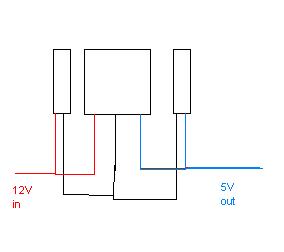
so how do I wire the cap?
do I put power to one lead of the cap, and connect the other lead to the regulator input, or would it be one lead of the cap to power, and one to the regulator ground?
KPierson 
Platinum - Posts: 3,527
Platinum spaceThis member consistently provides reliable informationspace
Joined: April 14, 2005
Location: Ohio, United States
Posted: May 02, 2009 at 5:28 PM / IP Logged  
Both caps need to be grounded and the other end of the cap needs to be connected to the correct power pin on the regulator.
Kevin Pierson
bigjohnny 
Copper - Posts: 293
Copper spacespace
Joined: September 23, 2008
Location: Ontario, Canada
Posted: May 02, 2009 at 5:39 PM / IP Logged  
So would it look something like this really doodiety diagram?
any 5v sources in the dash? -- posted image.
Page of 2

  Printable version Printable version Post ReplyPost New Topic
You cannot post new topics in this forum
You cannot reply to topics in this forum
You cannot delete your posts in this forum
You cannot edit your posts in this forum
You cannot create polls in this forum
You cannot vote in polls in this forum

  •  
Search the12volt.com
Follow the12volt.com Follow the12volt.com on Facebook
Friday, May 3, 2024 • Copyright © 1999-2024 the12volt.com, All Rights Reserved Privacy Policy & Use of Cookies
Disclaimer: *All information on this site ( the12volt.com ) is provided "as is" without any warranty of any kind, either expressed or implied, including but not limited to fitness for a particular use. Any user assumes the entire risk as to the accuracy and use of this information. Please verify all wire colors and diagrams before applying any information.

Secured by Sectigo
the12volt.com spacer
Support the12volt.com
Top
the12volt.com spacer