the12volt.com spacer
icon

staged nitrous control


Post ReplyPost New Topic
< Prev Topic Next Topic >
sportbikeryder 
Member - Posts: 2
Member spacespace
Joined: August 27, 2007
Posted: August 27, 2007 at 12:51 PM / IP Logged  

Hello,

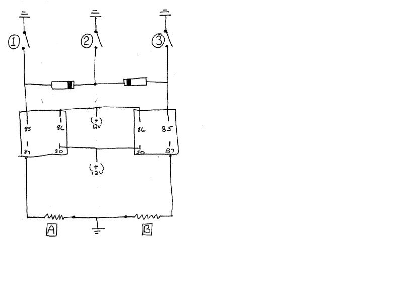
I am trying to hook up a three stage nitrous system on a motorcycle. I have three switched grounds corresponding to three different gears. I want to run one nitrous solenoid (A) in first, a second nitrous solenoid (B) in second, and both solenoids (A and B) in third, through relays to reduce current draw on switches. I think I need the diodes per the attached picture to prevent both solenoids from activating in each gear.  I have tried a search but didn't find anything related. Can someone confirm, correct, or add to my schematic?

Thanks,

Johnstaged nitrous control -- posted image.

Switch 1 = A energized

Switch 2 = B energized

Switch 3 = A + B energized

staged nitrous control -- posted image.

i am an idiot 
Platinum - Posts: 13,673
Platinum spaceThis member consistently provides reliable informationspace
Joined: September 21, 2006
Location: Louisiana, United States
Posted: August 27, 2007 at 1:41 PM / IP Logged  

The way you have it drawn this is what you have.

Switch 1 = A energized.   Switch 3 = B energized.  Switch 2 = A and B both energized.

We don't want you to flip the bike when shifting into 2nd gear.

sportbikeryder 
Member - Posts: 2
Member spacespace
Joined: August 27, 2007
Posted: August 27, 2007 at 2:24 PM / IP Logged  

Oops. Actually, I had it the other way (Labeled 1,3,2 across the top) in my preliminary sketch and that was the intent. I mostly just wanted to have another check on the diode orientation to be sure I am able to  isolate A and B individually and eliminate back feeding the relay.

Thanks for the catch on the switches.

John

i am an idiot 
Platinum - Posts: 13,673
Platinum spaceThis member consistently provides reliable informationspace
Joined: September 21, 2006
Location: Louisiana, United States
Posted: August 27, 2007 at 4:12 PM / IP Logged  
Your diodes are properly located and are in the right direction.

Sorry, you can NOT post a reply.
This topic is closed.

  Printable version Printable version Post ReplyPost New Topic
You cannot post new topics in this forum
You cannot reply to topics in this forum
You cannot delete your posts in this forum
You cannot edit your posts in this forum
You cannot create polls in this forum
You cannot vote in polls in this forum

  •  
Search the12volt.com
Follow the12volt.com Follow the12volt.com on Facebook
Tuesday, May 14, 2024 • Copyright © 1999-2024 the12volt.com, All Rights Reserved Privacy Policy & Use of Cookies
Disclaimer: *All information on this site ( the12volt.com ) is provided "as is" without any warranty of any kind, either expressed or implied, including but not limited to fitness for a particular use. Any user assumes the entire risk as to the accuracy and use of this information. Please verify all wire colors and diagrams before applying any information.

Secured by Sectigo
the12volt.com spacer
Support the12volt.com
Top
the12volt.com spacer