the12volt.com spacer
icon

rfid central locking.


Post ReplyPost New Topic
< Prev Topic Next Topic >
katq22 
Member - Posts: 6
Member spacespace
Joined: September 06, 2005
Location: Australia
Posted: July 09, 2008 at 7:31 PM / IP Logged  
I have purchased a cheap RFID kit off eBay that connects a relay (Basically outputs a small 12V current) when the token is put near the receiver, and disconnects after a time once the token is taken away.
How would I be able to set this up so that
1. When the relay is active a pulse is sent on the unlock signal
2. When removed a pulse is sent on the lock signal.
Thanks
Ben
i am an idiot 
Platinum - Posts: 13,672
Platinum spaceThis member consistently provides reliable informationspace
Joined: September 21, 2006
Location: Louisiana, United States
Posted: July 09, 2008 at 7:46 PM / IP Logged  
That is going to be a piece of cake. I will post you a picture in a couple hours. Unless somebody beats me to it. It is going to take 3 relays, 2 capacitors 2 diodes and 2 resistors. Hint Hint
katq22 
Member - Posts: 6
Member spacespace
Joined: September 06, 2005
Location: Australia
Posted: July 09, 2008 at 8:44 PM / IP Logged  
I am guessing it will use two of this setup linked together somehow. As it will be in a car it will need to be zero draw when in the locked state so as not to flatten the battery.
rfid central locking. -- posted image.
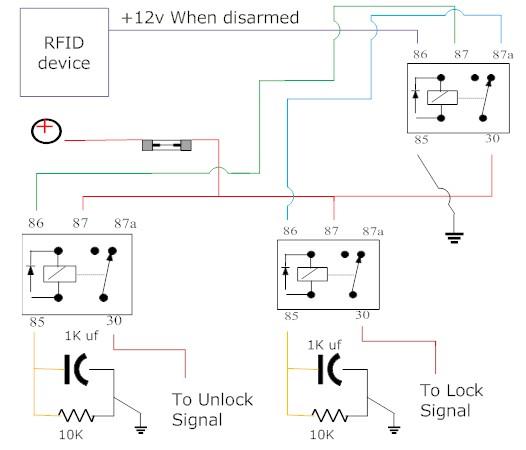
What program do you used for drawing diagrams? Are there any programs that you can make virtual circuits to test by turning the switch on and off?
i am an idiot 
Platinum - Posts: 13,672
Platinum spaceThis member consistently provides reliable informationspace
Joined: September 21, 2006
Location: Louisiana, United States
Posted: July 09, 2008 at 8:46 PM / IP Logged  

rfid central locking. -- posted image.

You will have to build 2 of the above.  1 will be for lock and the other for unlock.

There needs to be a third relay wired as follows.  If your rfid device outputs a positive voltage, that output wire to terminal 86 of the relay.  Ground terminal 85.  A Fused 12 volt constant source to terminal 30.  87A  goes to the lock momentary relay pictured above.  It connects to the wire labeled Switched 12v (+)      87 goes to that same wire on the momentary unlock relay pictured above.    If your device provides you a ground output or if you have any other questions, let me know.

i am an idiot 
Platinum - Posts: 13,672
Platinum spaceThis member consistently provides reliable informationspace
Joined: September 21, 2006
Location: Louisiana, United States
Posted: July 09, 2008 at 8:53 PM / IP Logged  
There will be minimal current draw when in the locked position.  It will be fractions of what an energized relay draws. 
katq22 
Member - Posts: 6
Member spacespace
Joined: September 06, 2005
Location: Australia
Posted: July 10, 2008 at 1:13 AM / IP Logged  
thanks for your rapid replys. Will this drain the battery if left for say a week or 2???
i am an idiot 
Platinum - Posts: 13,672
Platinum spaceThis member consistently provides reliable informationspace
Joined: September 21, 2006
Location: Louisiana, United States
Posted: July 10, 2008 at 5:02 AM / IP Logged  
The RFID device will pull way more current than the relay setup pulls. On paper the relays will draw 1.2 Milliamps of current. I will try to remember to build one today and give you an exact number. The 1000 mic cap may change the number a bit, but I do not think so. An energized relay draws 160 milliamps.
howie ll 
Pot Metal - Posts: 16,466
Pot Metal spacespace
Joined: January 09, 2007
Location: United Kingdom
Posted: July 10, 2008 at 5:34 PM / IP Logged  
Craig what am I not seeing here? Does the RFID unit supply the line to 85?
i am an idiot 
Platinum - Posts: 13,672
Platinum spaceThis member consistently provides reliable informationspace
Joined: September 21, 2006
Location: Louisiana, United States
Posted: July 10, 2008 at 5:42 PM / IP Logged  

He said it puts out a small 12 volt when the transmitter is in range.  Yes I am assuming that it puts out a positive voltage.  In my long post above, there is a third relay.  I have the RFID output wire going to 86  and ground to 85.  That relay depending on it's state will supply 12 volts to either one of the constant to momentary relays.

katq22 
Member - Posts: 6
Member spacespace
Joined: September 06, 2005
Location: Australia
Posted: July 10, 2008 at 9:19 PM / IP Logged  
So is this basically how it would work? and what sort of a pulse would that deliver? How long? long enough to drive door locks? Can the cap or resistor be changed to change the pulse length, and what Wattage should the resistor be?
Thanks so much for your help.
Ben
P.S. I found a Demo of Smart Draw to make this drawing. Man that program is expensive.
rfid central locking. -- posted image.
Page of 2

  Printable version Printable version Post ReplyPost New Topic
You cannot post new topics in this forum
You cannot reply to topics in this forum
You cannot delete your posts in this forum
You cannot edit your posts in this forum
You cannot create polls in this forum
You cannot vote in polls in this forum

  •  
Search the12volt.com
Follow the12volt.com Follow the12volt.com on Facebook
Tuesday, May 14, 2024 • Copyright © 1999-2024 the12volt.com, All Rights Reserved Privacy Policy & Use of Cookies
Disclaimer: *All information on this site ( the12volt.com ) is provided "as is" without any warranty of any kind, either expressed or implied, including but not limited to fitness for a particular use. Any user assumes the entire risk as to the accuracy and use of this information. Please verify all wire colors and diagrams before applying any information.

Secured by Sectigo
the12volt.com spacer
Support the12volt.com
Top
the12volt.com spacer