the12volt.com spacer
icon

understandin this alarm diagram


Post ReplyPost New Topic
< Prev Topic Next Topic >
h04n9 
Member - Posts: 7
Member spacespace
Joined: July 23, 2008
Location: British Columbia, Canada
Posted: July 23, 2008 at 4:35 PM / IP Logged  

Hi everyone, i'm a 1yr auto apprentice mechanic and this is my first time to attempt installing an alarm. The alarm I have is a LJ-8(no name I guess) alarm system that I receive from a friend, he purchase it a year ago online somewhere.

I'm trying to install this onto a 2003 Eclipse RS. I just needed something, a simple alarm system(keyless entry...) I'm having trouble with understanding the instruction of this diagram, sorry i'm very newbie!!:)

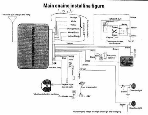
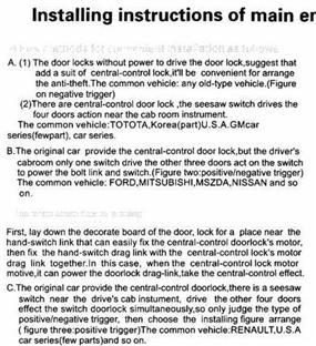
I've included the diagram(below) for this alarm. But i'm not sure how/where to, the Relay get hook up to...also in the 2nd image link, I dont understand how to power lock goes.

Could someone please show me where to hook the relay and the power lock for this system onto 03Eclipse. As I have alldata and Mitchell on demand so i can look up for thing if needs too.

thanks in advance

h04n9 
Member - Posts: 7
Member spacespace
Joined: July 23, 2008
Location: British Columbia, Canada
Posted: July 23, 2008 at 4:40 PM / IP Logged  

sorrie, the link works but I didn't know how to add it properly

have to copy and paste into address bar for it to work. thanks

the12volt 
Administrator - Posts: 3,955
Administrator spaceThis member has made a donation to the12volt.com. Click here for more info.spaceThis member has been recognized as an authority in Electrical Theory. Click here for more info.spaceThis member has been recognized as an authority in Mobile Audio and Video. Click here for more info.spaceThis member has been recognized as an authority in Mobile Security and Convenience. Click here for more info.spacespace
Joined: March 07, 2002
Location: Louisiana, United States
Posted: July 23, 2008 at 5:20 PM / IP Logged  
Use this button to add images to your post: understandin this alarm diagram -- posted image.
understandin this alarm diagram -- posted image. the12volt • Support the12volt.com
h04n9 
Member - Posts: 7
Member spacespace
Joined: July 23, 2008
Location: British Columbia, Canada
Posted: July 24, 2008 at 2:50 AM / IP Logged  

understandin this alarm diagram -- posted image.

understandin this alarm diagram -- posted image.

KarTuneMan 
Platinum - Posts: 7,056
Platinum spaceThis member has made a donation to the12volt.com. Click here for more info.spaceThis member consistently provides reliable informationspace
Joined: December 14, 2004
Location: Isle Of Man
Posted: July 24, 2008 at 11:46 AM / IP Logged  

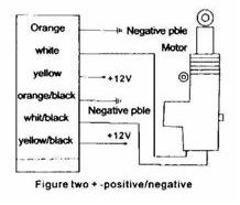
You unit has built in lock/unlock relays. This is why there are 6 wires. The six wires represent pins on a standard relay. 87, 87a, and 30. Normally open, normally closed, and common.

You locks are negative pulse. Take the 2 wires labeled N.O. and ground them. One of the 2 is for lock, the other for unlock.

You will NOT USE the N.C. This leaves the common.... on is your lock trigger, the other is unlock.

There is a black plug in the drivers kick. Lock is purple, unlock is GREEN/ red.

h04n9 
Member - Posts: 7
Member spacespace
Joined: July 23, 2008
Location: British Columbia, Canada
Posted: July 26, 2008 at 12:14 AM / IP Logged  

This is the other diagram that i couldn't upload, I resize them differently, hopefully it will work this time.

understandin this alarm diagram -- posted image.

h04n9 
Member - Posts: 7
Member spacespace
Joined: July 23, 2008
Location: British Columbia, Canada
Posted: July 26, 2008 at 12:35 AM / IP Logged  

Hi Kartune, THANKS for the reply. I took a look at the black plug and have locate the Lock/Unlock wires. I won't work on this until I know where to connect all the wires.

From the diagram, N.O which is the Orange+ORANGE / blck to ground. Which one should i leave out?

Also the diagram in the third post, there's a relay in the top-right corner. I dont understand how to connect them. I dont know if this is right, so Yellow from alarm to Yellow of Relay, White of alarm to White of relay, Green of Relay to Green(+) of Ignition switch Harness??? Then there is another Green of Relay and Green from alarm that doesn't show going anywhere. What is this relay for, starter kill?

thanks

KarTuneMan 
Platinum - Posts: 7,056
Platinum spaceThis member has made a donation to the12volt.com. Click here for more info.spaceThis member consistently provides reliable informationspace
Joined: December 14, 2004
Location: Isle Of Man
Posted: July 26, 2008 at 12:40 AM / IP Logged  
Leave out BOTH normally closed. (87a)
h04n9 
Member - Posts: 7
Member spacespace
Joined: July 23, 2008
Location: British Columbia, Canada
Posted: July 26, 2008 at 12:57 AM / IP Logged  

KarTune, I don't know much about electrical yet. Can you be abit patient with me...understandin this alarm diagram -- posted image.

How do i know out of the six wires which one is 87a NClosed? I have posted a new diagram 2 post up, please take a look?

Could you also explain to me for the relay in the first diagram please?understandin this alarm diagram -- posted image.

h04n9 
Member - Posts: 7
Member spacespace
Joined: July 23, 2008
Location: British Columbia, Canada
Posted: July 27, 2008 at 2:42 PM / IP Logged  
How/where do i connect the relay, for the first diagram in the 4th post (right top corner), please someone help? thnaks

Sorry, you can NOT post a reply.
This topic is closed.

  Printable version Printable version Post ReplyPost New Topic
You cannot post new topics in this forum
You cannot reply to topics in this forum
You cannot delete your posts in this forum
You cannot edit your posts in this forum
You cannot create polls in this forum
You cannot vote in polls in this forum

  •  
Search the12volt.com
Follow the12volt.com Follow the12volt.com on Facebook
Friday, May 17, 2024 • Copyright © 1999-2024 the12volt.com, All Rights Reserved Privacy Policy & Use of Cookies
Disclaimer: *All information on this site ( the12volt.com ) is provided "as is" without any warranty of any kind, either expressed or implied, including but not limited to fitness for a particular use. Any user assumes the entire risk as to the accuracy and use of this information. Please verify all wire colors and diagrams before applying any information.

Secured by Sectigo
the12volt.com spacer
Support the12volt.com
Top
the12volt.com spacer