the12volt.com spacer
icon

unlock wire diode splitting mr2 92


Post ReplyPost New Topic
< Prev Topic Next Topic >
deusv 
Member - Posts: 4
Member spacespace
Joined: April 07, 2010
Location: United Kingdom
Posted: April 07, 2010 at 4:53 AM / IP Logged  
Hi all,
I'm installing an alarm into a 1992 Toyota MR2 Turbo (Jap Import). The wiring colours are here:
https://www.the12volt.com/installbay/alarmdetail/2102.html
However, since this is a Jap import, the extra information below that I found somewhere else is required:
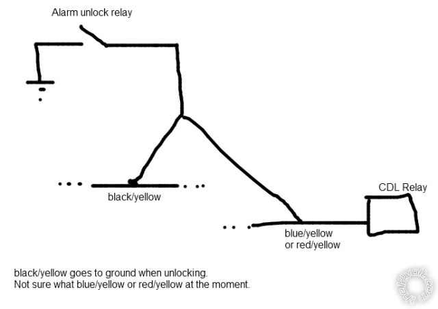
CDL Notes IMPORT MODELS - UNLOCK WIRE NEEDS DIVIDING BY 2 DIODES. 1 DIODE TO UNLOCK. 1 DIODE TO BLUE / YELLOW OR RED / YELLOW ON CDL RELAY.
My question is where and which orientation these diodes go?
Note: If I wire the alarm unlock directly to yellow/black and nowhere else, it will only work once before requiring a manual lock/unlock to work again - I think this is why the diodes are needed.
I have attached a crude diagram of how I think the system is supposed to be wired without the diodes.
unlock wire diode splitting mr2 92 -- posted image.
Any help will be much appreciated!
tedmond 
Gold - Posts: 4,610
Gold spaceThis member has been recognized as an authority in Mobile Security and Convenience. Click here for more info.spacespace
Joined: January 06, 2007
Location: Ontario, Canada
Posted: April 07, 2010 at 5:51 AM / IP Logged  

place diode silver band towards alarm.

https://www.the12volt.com/diodes/diodes.asp
Ted
2nd Year Tier 1 Medical School
Still installing as a hobby...pays for groceries
Compustar Expert
deusv 
Member - Posts: 4
Member spacespace
Joined: April 07, 2010
Location: United Kingdom
Posted: April 07, 2010 at 5:55 AM / IP Logged  
Thank you for your quick reply. I'll try it out tonight!
howie ll 
Pot Metal - Posts: 16,466
Pot Metal spacespace
Joined: January 09, 2007
Location: United Kingdom
Posted: April 07, 2010 at 8:48 AM / IP Logged  
I find this very hard to understand, the only time you would need diodes would be if you were using a DEI product with just the flip flop (2 wire) rather than relay driven outputs. I did an alarm R/S in one recently, I've done about 25 of these over the years and NEVER needed diodes.
deusv 
Member - Posts: 4
Member spacespace
Joined: April 07, 2010
Location: United Kingdom
Posted: April 07, 2010 at 9:16 AM / IP Logged  
Believe me I wish I didn't have to use diodes - but if I only connect the (-) unlock output to yellow/black then it doesn't work properly. As mentioned, it will work the first time but after that you have to manually lock with the key and/or cycle the ignition before you can unlock with the fob. This is the 3rd time installing an alarm onto this car and the previous 2 had the same problem. This time I hope to get it right - I'll let you know how it goes.
If you're interested, I have the official circuit diagram of the vehicles door lock system which I would be happy to upload if you would like to have a look. The only thing is that it's for US spec cars, though most of it should be the same.
howie ll 
Pot Metal - Posts: 16,466
Pot Metal spacespace
Joined: January 09, 2007
Location: United Kingdom
Posted: April 07, 2010 at 1:07 PM / IP Logged  
This is starting to wiz me off, I even checked Directechs for confirmation. Just take a 12volt test light one side to ground then probe the plugs in the driver's kick panel. One wire will give you lock, the other unlock, NO DIODES that's it. Just one question, what brand and model of alarm?
All regional variations, Japanese, US and Europe used the same locking systems, Euro versions had a factory alarm module in the right side rear quarter, giving you back trunk, engine bay, front(?) and door triggers.
deusv 
Member - Posts: 4
Member spacespace
Joined: April 07, 2010
Location: United Kingdom
Posted: April 07, 2010 at 3:53 PM / IP Logged  
Well I've installed as per above with the diodes and it works perfectly at last! I used the blue / YELLOW wire to the CL relay in the end - not sure if the RED / yellow one would work too.
I did try it without the diodes and it just didn't work. I'm not sure if you could pulse positive for unlock/lock - I've only ever used pulse negative before and that's all wiring info. I have looked at says.
I should add that this mr2 turbo is a Japanese import and I have found in the past that much of the wiring is inconsistent with the schematics for the US turbo. Wiring for non-turbos/euro models is different too.
The alarm is an ebay jobbie, it's an "FM 2-way pager":
http://#.co.uk/ws/eBayISAPI.dll?ViewItem&item=360185185163
(Item number 360185185163 if link doesn't work)
The door outputs are simple relays, 6 wires in total, 2 of which (NC) are not used. NO are connected to the lock/unlock wires and commons are connected to ground.
tedmond 
Gold - Posts: 4,610
Gold spaceThis member has been recognized as an authority in Mobile Security and Convenience. Click here for more info.spacespace
Joined: January 06, 2007
Location: Ontario, Canada
Posted: April 07, 2010 at 4:08 PM / IP Logged  
hey howard, some jap cars use 2 wires for unlock. one is unlock itself and one is the lock detection wire where it will sense a key. on the new hondas, you need to diode isolate the wires just like this car i assume.
Ted
2nd Year Tier 1 Medical School
Still installing as a hobby...pays for groceries
Compustar Expert
howie ll 
Pot Metal - Posts: 16,466
Pot Metal spacespace
Joined: January 09, 2007
Location: United Kingdom
Posted: April 08, 2010 at 2:28 AM / IP Logged  
Priority unlock back in 92? Also keysense hasn't been mentioned, all I can repeat is that I've done 2 dozen, many were imports, never needed diodes.

Sorry, you can NOT post a reply.
This topic is closed.

  Printable version Printable version Post ReplyPost New Topic
You cannot post new topics in this forum
You cannot reply to topics in this forum
You cannot delete your posts in this forum
You cannot edit your posts in this forum
You cannot create polls in this forum
You cannot vote in polls in this forum

  •  
Search the12volt.com
Follow the12volt.com Follow the12volt.com on Facebook
Tuesday, May 21, 2024 • Copyright © 1999-2024 the12volt.com, All Rights Reserved Privacy Policy & Use of Cookies
Disclaimer: *All information on this site ( the12volt.com ) is provided "as is" without any warranty of any kind, either expressed or implied, including but not limited to fitness for a particular use. Any user assumes the entire risk as to the accuracy and use of this information. Please verify all wire colors and diagrams before applying any information.

Secured by Sectigo
the12volt.com spacer
Support the12volt.com
Top
the12volt.com spacer