the12volt.com spacer
icon

viper 5901 wiring on 2010 honda ridgeline


Post ReplyPost New Topic
< Prev Topic Next Topic >
chiefwigms 
Member - Posts: 9
Member spacespace
Joined: June 29, 2010
Location: Colorado, United States
Posted: June 29, 2010 at 10:51 AM / IP Logged  

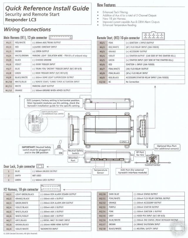
I was wondering if anyone that's installed a 5901 could go over the wiring below (for a 2010 ridgeline rtl).. i'm not sure about some of the connections:

viper 5901 wiring on 2010 honda ridgeline -- posted image.

H1/ 1 -> *not used

H1/ 2 -> (+) 12V, White, IGN
H1/ 3 -> TO DEI SIRENS (5901 + 513T)
H1/ 4 -> *not used
H1/ 5 -> Chassis Ground
H1/ 6 -> *not used
H1/ 7 -> TO DEI TILT (507M)/DEI BACKUP BATTERY (520T)
H1/ 8 -> *not used
H1/ 9 -> DOME SUPERVISION RELAY (is this needed?)
H1/10 -> *not used
H1/11 -> *not used
H1/12 -> TO DEI BACKUP BATTERY (520T)

H2/ 1 -> *not used

H2/ 2 -> *not used
H2/ 3 -> *not used
H2/ 4 -> *not used
H2/ 5 -> *not used
H2/ 6 -> *not used
H2/ 7 -> *not used
H2/ 8 -> *not used
H2/ 9 -> TACHOMETER Input (is this needed)?
H2/10 -> *not used
H2/11 -> *not used
H2/12 -> *not used
H2/13 -> *not used
H2/14 -> *not used
H2/15 -> Hood Pin Switch
H2/16 -> *not used
H2/17 -> (+) Brake Wire, Light Blue Pin 26, Brake Switch
H2/18 -> Chassis Ground

H3/ 1 -> ???

H3/ 2 -> ???
H3/ 3 -> (+) Accessory, Yellow, IGN
H3/ 4 -> (+) Starter (ECM Side), BLACK/ White, IGN
H3/ 5 -> (+) Starter (Car Side), BLACK/ White, IGN
H3/ 6 -> (+) Ignition, BLACK / YELLOW, IGN
H3/ 7 -> ???
H3/ 8 -> ???
H3/ 9 -> ???
H3/10 -> *not used

Door Lock Harness

None

CANMAX400 DEI

11 -> CAN BUS SW (Data), BROWN / Black Pin 4 (dash fuse box)
14 -> Immobilizer Data, RED / Blue Pin 2 (ICU)
16 -> (-) Security Light Key Side, Light Blue/Orange Pin 5 (ICU)
20 -> (-) Security Light ECM Side, Light Blue/Orange Pin 5 (ICU)

nstalling :

VIPER 5901 w/ CANMAX400DEI
506T GLASS-BREAK SENSOR (goes to the optional port on the 5901)
507M TILT SENSOR
520T BACKUP BATTERY
513T MINI PIEZO SIREN

Questions:

1) There is a "Light Polarity Fuse" under where the CANMAX400DEI goes on the 5901- is this needed for a ridgeline? if so, what should this be set to?
3) Is the Tach Input on H2 needed? The CANMAX400DEI manual says D2D handles the Tach Output, and since it's a dockable module, do I need to connect anything? (i've been researching, and some people just loop back the tach from the w2w wire, but they don't use the DEI versioN)
4) I'm not sure about pins 1,2,7,8,9 on the remote start wiring... anyone have any ideas?
5) For the Hood Pin Switch on H2/15, can the D2D bus recognize this (the wiring info below says there's a wire i can connect to, or install a separate one provided with the 5901)?

the 2009 ridgeline's wiring is the same as 2010 i believe ( here):

12 Volts  white  (+)  ign
Starter  BLACK/ white  (+)  ign
Ignition  BLACK / YELLOW  (+)  ign
Accessory  yellow  (+)  ign
Second Accessory  WHITE/ black  (+)  ign

Any other comments or suggestions are helpful - this is my first install, so i'd like to make sure everything goes smoothly

Thanks!

-Pete

buddholly 
Copper - Posts: 244
Copper spacespace
Joined: August 24, 2006
Location: United States
Posted: June 30, 2010 at 9:13 AM / IP Logged  
light polarity fuse, is for your parking lights and depends on what wire you hit for them, that vehicle has two, blue (-), or RED / black (+), put the fuse in the jumper depending on what wire you hit.
The tach input is done by the canmax so is the hood pin and brake wire. Dome supervision is optional.
All red, RED / white, RED / black go to 12v constant.
Pink goes to ignition (BLACK / YELLOW)
Pink/white goes to second ignition. (or is programmable to do second accessory which is orange)
Pink/black isn't needed.
D2D does all this:
DL-Arm Factory Security
DL-Disarm Factory Security
DL-Door Lock Control
DL-Door Unlock
DL-Driver Priority Unlock
FOB-CAN Alarm Control w/ FOB remote
PK-Immobilizer Bypass-Data No Key Req'd
RS-Tach / RPM Output
SS-CAN Alarm control w/ FOB remote
SS-Entry Monitoring ALL Door Pins
SS-Entry Monitoring Driver Door Pin
SS-Entry Monitoring Hood Pin
ST-Brake Status (foot brake)
ST-Ignition Status
chiefwigms 
Member - Posts: 9
Member spacespace
Joined: June 29, 2010
Location: Colorado, United States
Posted: July 01, 2010 at 7:10 PM / IP Logged  

thanks!

so just to be sure:

H1/9 BLACK/ WHITE (-) 200mA DOME LIGHT SUPERVISION OUTPUT -> optional (i don't care if the dome light turns on with the alarm)

H1/11 WHITE PARKING LIGHT OUTPUT -> if i don't wire this, will the lights still flash (using the factory alarm?)

All Optional: 

H2/9 VIOLET/WHITE TACHOMETER INPUT
H2/15 GREY (-) HOOD PIN INPUT (N/C OR N/O)
H2/17 BROWN (+) BRAKE SHUTDOWN INPUT
Needs to Be Wired:
H2/18 BLACK/ WHITE (-) NEUTRAL SAFETY INPUT

buddholly 
Copper - Posts: 244
Copper spacespace
Joined: August 24, 2006
Location: United States
Posted: July 02, 2010 at 11:08 AM / IP Logged  
BLACK/ White is optional, the canmax might actually do it for you.
White is for your parking lights, so when you remote start the car the lights come on, or they flash when you lock/unlock. I would hook it up to the negative parking light white (blue) which is at the light switch. Make sure the jumper under the cover on the 5901 is set to the negative jumper.
Violet/White is done by the canmax.
Grey is done by the canmax.
Brown is done by the canmax.
h2/18 BLACK/ White goes to ground.
chiefwigms 
Member - Posts: 9
Member spacespace
Joined: June 29, 2010
Location: Colorado, United States
Posted: July 18, 2010 at 1:59 AM / IP Logged  

so a quick update -

I did the install today, and am having problems with the remote start - the car will r/s but the starter keeps going, then dies after 10 sec... does this 3 times then fails.

I tried resetting the virtual tach (open door, turn key to on, within 5 sec press control, press & hold control, then press control 4x, then press & hold control again and shut off) with the same results

With the bitwriter, its set to virtual tach - i don't think it ever learned successfully cause i never saw the parking lights stay on or the led a solid blue (it always dies after 10 sec)

any ideas?

chiefwigms 
Member - Posts: 9
Member spacespace
Joined: June 29, 2010
Location: Colorado, United States
Posted: July 18, 2010 at 5:31 PM / IP Logged  

so another update -

with the key in the on position, the r/s keeps cranking but after like 5 seconds stops, and the car is started, but since the key is in the ignition, the r/s just shuts off, and never learns

if i try without the key in the ignition, the same thing happens above (tries 3x for 10 sec then dies)

i'm lost on this one

Mark Mizenko 
Copper - Posts: 460
Copper spacespace
Joined: October 13, 2004
Location: Pennsylvania, United States
Posted: July 18, 2010 at 8:55 PM / IP Logged  

You can use the Voltage Sensing setting, set for .08 crank time, Voltage Check  set for Low.

Are you sure you have the correct wire (purple) connected to the starter wire?

I'm not really to clear on what your problem can be.  I'm not a fan of the CANMAX stuff OR wiring D2D with DEI stuff.  I wire that W2W, and never have had a problem

chiefwigms 
Member - Posts: 9
Member spacespace
Joined: June 29, 2010
Location: Colorado, United States
Posted: July 18, 2010 at 11:40 PM / IP Logged  

Tried the .8 crank time, and the voltage check i couldn't find - i saw a smart start voltage, but i wasn't in that mode (f 3 times then remote start), i was just trying a normal remote start.

I probed the wiring during key positions/ start and found (h3 harness);

Pins 2/6/9 Always had +12V

During Off : 1,3,4,5,7 = 0V

During I : 7 = 12V; 3,4,5 = 0V
During II : 3,4,7 = 12V, 5 = 0V
When R/S : 3,4,7 = 12V, 5 = 0V

When Starting via Key, pin 5 had 12V.

just to update

H1/ 1 -> *not used

H1/ 2 -> (+) 12V, White, IGN
H1/ 3 -> TO DEI SIRENS (5901 + 513T)
H1/ 4 -> *not used
H1/ 5 -> Chassis Ground
H1/ 6 -> *not used
H1/ 7 -> TO DEI TILT (507M)/DEI BACKUP BATTERY (520T)
H1/ 8 -> *not used
H1/ 9 -> *not used
H1/10 -> *not used
H1/11 -> Parking Light Switch (-)
H1/12 -> TO DEI BACKUP BATTERY (520T)

H2/ 1 -> *not used

H2/ 2 -> *not used
H2/ 3 -> *not used
H2/ 4 -> *not used
H2/ 5 -> *not used
H2/ 6 -> *not used
H2/ 7 -> *not used
H2/ 8 -> *not used
H2/ 9 -> *not used
H2/10 -> *not used
H2/11 -> *not used
H2/12 -> *not used
H2/13 -> *not used
H2/14 -> *not used
H2/15 -> *not used
H2/16 -> *not used
H2/17 -> *not used
H2/18 -> Chassis Ground

H3/ 1 -> (+) Ignition, BLACK / YELLOW

H3/ 2 -> +12V, White
H3/ 3 -> (+) Accessory, Yellow
H3/ 4 -> (+) Starter, BLACK/ White (Car Side)
H3/ 5 -> (+) Starter,BLACK/ White (Key Side)
H3/ 6 -> +12V, White
H3/ 7 -> (+) Second Accessory,
H3/ 8 -> *not used
H3/ 9 -> +12V, White
H3/10 -> *not used

CANMAX400 DEI

11 -> CAN BUS SW (Data), BROWN / Black Pin 4 (dash fuse box)
14 -> Immobilizer Data, RED / Blue Pin 2 (ICU)
16 -> (-) Security Light Key Side, Light Blue/Orange Pin 5 (ICU)
20 -> (-) Security Light ECM Side, Light Blue/Orange Pin 5 (ICU)

Mark Mizenko 
Copper - Posts: 460
Copper spacespace
Joined: October 13, 2004
Location: Pennsylvania, United States
Posted: July 19, 2010 at 11:58 AM / IP Logged  

I dont wanna sound silly, but can you post the wire COLORS, not numbers.  I forgot all the numbers about 20 years ago.

The color wires from the module connected to the color wires in the car.

And... the readings you get on your meter from the ignition switch wires should be the exact same, as when you start with the key, as you do when you remote start.  Power must be present, appear and disappear at the same times as using the key.

chiefwigms 
Member - Posts: 9
Member spacespace
Joined: June 29, 2010
Location: Colorado, United States
Posted: July 21, 2010 at 8:57 AM / IP Logged  

thanks for all your guys' help

i didn't realize that with the canmax400dei, you need to set the tach option w/ the bit writer to "tach" instead of virtual tach.  did that and everything works like a charm!

Page of 2

  Printable version Printable version Post ReplyPost New Topic
You cannot post new topics in this forum
You cannot reply to topics in this forum
You cannot delete your posts in this forum
You cannot edit your posts in this forum
You cannot create polls in this forum
You cannot vote in polls in this forum

  •  
Search the12volt.com
Follow the12volt.com Follow the12volt.com on Facebook
Saturday, April 27, 2024 • Copyright © 1999-2024 the12volt.com, All Rights Reserved Privacy Policy & Use of Cookies
Disclaimer: *All information on this site ( the12volt.com ) is provided "as is" without any warranty of any kind, either expressed or implied, including but not limited to fitness for a particular use. Any user assumes the entire risk as to the accuracy and use of this information. Please verify all wire colors and diagrams before applying any information.

Secured by Sectigo
the12volt.com spacer
Support the12volt.com
Top
the12volt.com spacer