the12volt.com spacer
icon

2010 f250 diesel cc al 1810 edp, pkall


Post ReplyPost New Topic
< Prev Topic Next Topic >
dafaic 
Member - Posts: 20
Member spacespace
Joined: January 25, 2011
Location: Texas, United States
Posted: January 25, 2011 at 11:47 PM / IP Logged  

I have been reading this site for days and got really great tips.  I have learned alot from this site and recommendations.  I now have everything in hand to make this install happen.  I have truck wiring from bull dog, alarm brain diagram from Excalibur, and vehicle specific sheet for pkall. 

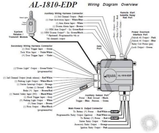
Will be using D2D between pkall and brain.  The pkall calls for the blue/white to connect to a (-) while running.  After looking through the alarm diagram I don't see a (-) while running nor on the trucks wiring.  I was considering setting up a relay to convert switched ignition to a negative output for this connection?  Another possible option is to connect this to the horn output which is (-) and since this is a programmable out, change the alarm to show it as an ignition out?

I understand I need to cut the blue/white for the starter which is at the ign switch/grey 10 pin plug/ #10 pin.  The starter side will go to the violet wire on the main output connector  of the alarm brain labeled starter relay output.  After looking over the diagram there is no ignition input.  It does appear there is a (-) start activation input.  Should I use a relay to convert this positive ign wire from ign switch to a negative and connect to the WHITE/ blue on the aux wiring harness of the alarm brain?

Can I connect both the acc heater blower 1 and 2 (from ignition switch 10 pin plug pins 7 and 5) (#1 BROWN / yellow or yellow orange) (#2 PURPLE / green)to the single orange accessory relay out of the alarm brain? 

I am only going to use single unlock so that is (-)yellow/purple from truck to blue wire on power door lock interface.  I'll have to test the alarm to see what the polarity is as it is not indicated on diagram.

lock is (-)blue/green connected to green on power door lock interface.  will have to test polarity to insure alarm outputs (-) signal. 

The alarm hood trigger input is (-).  I would like to use the factory hood trigger.  Any info on the factory hood trigger would be appreciated as it's not posted anywhere I've seen.

I certainly appreciate all the help...

2010 f250 6.4 cc
Twelvoltz 
Platinum - Posts: 2,384
Platinum spaceThis member has made a donation to the12volt.com. Click here for more info.spaceThis member consistently provides reliable informationspace
Joined: March 24, 2005
Location: New Jersey, United States
Posted: January 26, 2011 at 7:48 AM / IP Logged  
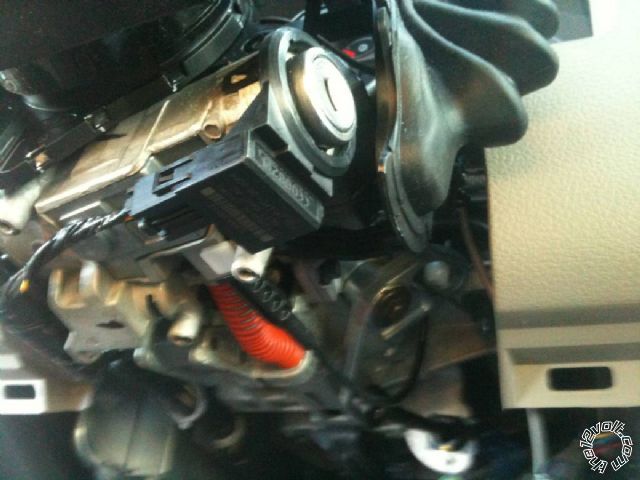
Before you do the bench wire take apart the truck. Take a look at the ignition key cylinder, tell me if you see a pickup antenna for transponder. I have yet to see a diesel that has a transponder. I know it has the light in the dash, and the keys have chips in them...but I have yet to come across one that actually had the pickup ring in the truck. If there is no transponder ring, you do not need the transponder bypass. If for some reason you do need the bypass, hooking it up D2D would not require hard wiring a ground when running.
That truck also has factory anti-grind, anti under crank, and anti over crank. To test it...turn the ignition key to on, wait for the wait to start indicator to go out and just tap the key to the start position and let go. You should see the vehicle crank the starter and disengage it when started.
Door Locks in your truck are negative pulsed. If your system has 'flip-flop' outputs, add diodes (cathode side facing brain of system) and hook the wires direct to the truck. Flip-flop outputs are outputs that will provide a ground pulse when locking and the same wire would provide a positive output when unlocking. I am pretty sure yours does not have this, so diodes would not be necessary.
As far as the hood pin is concerned...if the truck is equipped, it would be a blue/orange wire at the switch or smart junction box in the passenger kick panel in a black 26 pin plug, pin 10.
dafaic wrote:
I understand I need to cut the blue/white for the starter which is at the ign switch/grey 10 pin plug/ #10 pin. The starter side will go to the violet wire on the main output connector of the alarm brain labeled starter relay output. After looking over the diagram there is no ignition input. It does appear there is a (-) start activation input. Should I use a relay to convert this positive ign wire from ign switch to a negative and connect to the WHITE/ blue on the aux wiring harness of the alarm brain?
As far as cutting the vehicle's starter wire, it's really up to you, by cutting the wire it would add a layer of protection as it would add starter kill when the system is armed...but again, your truck is equipped with factory anti-grind. Simply hooking the purple from your Excalibur to the vehicle's starter wire would get your system up and running. Ignition 'input' is achieved by hooking up the ignition output to the vehicle...the remote start monitors that wire for ignition input.   If you wanted to use the factory remote to activate remote start you would use the negative start activation input. I am not familiar with Excalibur but if your system came with it's own remotes you do not have to connect anything to this wire.
Installer, IT support, and FFL. I need less hobbies.
dafaic 
Member - Posts: 20
Member spacespace
Joined: January 25, 2011
Location: Texas, United States
Posted: January 26, 2011 at 9:06 AM / IP Logged  

I took apart the colum and attached a picture.  The truck does in fact have the tip start feature and I love it.  Blip the key and the truck self starts or cranks for upto 30seconds.   From other forums I've read the 08+ need the bypass even the diesel. 

2010 f250 diesel cc al 1810 edp, pkall -- posted image.

The D2D does not require any hard wiring 4pin plug from bypass to alarm brain.  But the bypass has a 7 pin plug also which xpresskit shows 4 need to be wired to the ignition switch (power/ground/rx/tx) and 1 wire a blue/white needs to go to a (-) while running.  On some alarms it is known as a remote start status output.

Door locks are seperate negative wires for lock/unlock and alarm has outs I'll just have to determine if the outs are negative or not.

Thank You for hood pin info and the info relating to just taping the starter wire!  I will go that route!

2010 f250 6.4 cc
Twelvoltz 
Platinum - Posts: 2,384
Platinum spaceThis member has made a donation to the12volt.com. Click here for more info.spaceThis member consistently provides reliable informationspace
Joined: March 24, 2005
Location: New Jersey, United States
Posted: January 26, 2011 at 9:26 AM / IP Logged  
Over the past few weeks I have done a 09 F250 Diesel, a 10 F350 diesel, and an 08 V10 none had the transponder. Yours definitely does.
For the bypass power/ground/ignition/gwr connections I always connect these during my bench wiring, leaving only the TX and RX to connect in the vehicle. What's odd is that typically in D2D mode the gwr is run over data...that module does not run it over the D2D connection. I would just hook up the entire bypass W2W as it is only a power and ground connection that the D2D is saving you...and again you can do this on the bench.
To your question about the gwr output, even the cheap chinese manufactured systems I have seen include some type of low current negative output to activate a bypass. Can you post the wiring diagram for your particular system. Someone here should be able to offer you assistance in identifying that connection, or at least suggest what to use in place of it.
Installer, IT support, and FFL. I need less hobbies.
dafaic 
Member - Posts: 20
Member spacespace
Joined: January 25, 2011
Location: Texas, United States
Posted: January 26, 2011 at 7:36 PM / IP Logged  

My friend suggested using the starter interupt for the (-) ground while running?  I sure do appreciate all the help!  I see now what your talking about on the D2D.  Manual states if you have to W2W then cut the plug off and hook up + and -.  Can i hook both trucks accessory blower wires to the alarms accessory relay out (orange) on the main power & output connector? 

2010 f250 diesel cc al 1810 edp, pkall -- posted image.

2010 f250 6.4 cc
Twelvoltz 
Platinum - Posts: 2,384
Platinum spaceThis member has made a donation to the12volt.com. Click here for more info.spaceThis member consistently provides reliable informationspace
Joined: March 24, 2005
Location: New Jersey, United States
Posted: January 26, 2011 at 8:43 PM / IP Logged  
On the 'Remote Start Satellite Relay Port Red Plug' there is a wire labeled "ignition output -". Use this for your gwr.
To you question about the second accessory wire: No, NEVER combine wires in the ignition switch, they are isolated from the manufacturer for a reason. If you system does not have enough outputs to supply these wires, relays are required. However, according to my sheet, your truck has one starter (blue/white), one ignition (WHITE/ orange), and two accessory wires (BROWN / yellow or yellow/orange and PURPLE / green). Your system has the ability to supply these wires without the need for additional relays. Use the Pink/White for second accessory and reprogram it to operate as accessory.
Installer, IT support, and FFL. I need less hobbies.
dafaic 
Member - Posts: 20
Member spacespace
Joined: January 25, 2011
Location: Texas, United States
Posted: January 27, 2011 at 12:35 PM / IP Logged  

I looked at the diagram again I see the ignition out you speak of.  It doesn't state what the polarity is as I believe they left off the color of the wire after that dash since it conflicts with the bold title.  But I will determine polarity and switch it if necessary to use as the GWR. 

Will do on the accessory. 

Will tapping into the 12 volt constant black 1 pin plug (h) pin 1 in the sjb work for both of my main battery connections? 

Not sure if all the F250's are this way but if I lock the door for example I parked at a gas station in a not so good area and left my sister in law and my son in truck while wife and I ran in real quick.  Used keypad to lock truck.  Couple minutes later while we were still inside my son opens his door and trucks lights and horn go off.  So I am assuming I have a full fledged oem security?  So the excalibur will need to be hooked upto to disarm the factory alarm through the GREEN/ purple (-) in the sjb 26pin grey #8. 

Again I really appreciate all the fine advice!  And clearly from someone that works on these day in and day out including my own kind.

2010 f250 6.4 cc
monty_77 
Copper - Posts: 491
Copper spaceThis member has made a donation to the12volt.com. Click here for more info.spacespace
Joined: January 15, 2009
Location: North Dakota, United States
Posted: January 28, 2011 at 1:12 AM / IP Logged  
your truck will not have the GREEN/ purple wire for disarm
you will have to use a relay to power the iginiton and ground the bypass at the same time to disarm
disarm wire of the alarm to trigger relay(below) and grw of bypass(use a diode to seperate the bypass and relay
relay
85 alarm disarm wire
86 12v
87 12v
30 ignition of truck
Twelvoltz 
Platinum - Posts: 2,384
Platinum spaceThis member has made a donation to the12volt.com. Click here for more info.spaceThis member consistently provides reliable informationspace
Joined: March 24, 2005
Location: New Jersey, United States
Posted: January 28, 2011 at 6:48 AM / IP Logged  
To expand a little on monty_77's post...
Where did you get the information that says you have a factory disarm wire? The sheets I use do not list one, as monty_77 stated...you have to energize ignition and provide the transponder information to the vehicle to disarm the factory alarm. Audiovox has a diagram of one way to achieve this here.
dafaic wrote:
I looked at the diagram again I see the ignition out you speak of. It doesn't state what the polarity is as I believe they left off the color of the wire after that dash since it conflicts with the bold title. But I will determine polarity and switch it if necessary to use as the GWR.
It's always a good idea to verify every connection with a DMM...but looking at the configuration of your system I am certain it will be a low current negative.
Yes you can get your constant +12V inputs from a single source, as long as the wire you are grabbing supply from can handle the load. You would also want to change the fuses to match what the vehicle's ignition is rated for. In your case, take out the 30 amp fuses and replace them with 20 amp.
dafaic wrote:
And clearly from someone that works on these day in and day out including my own kind.
Although the compliment is appreciated, I feel I must be honest. This is a hobby for me. I used to work at a local specialty shop but that was a long time ago(my MECP certification expired in 2000). I still do quite a few remote starts, and the occasional head unit, but just after work and on weekends.
Installer, IT support, and FFL. I need less hobbies.
dafaic 
Member - Posts: 20
Member spacespace
Joined: January 25, 2011
Location: Texas, United States
Posted: January 28, 2011 at 6:59 AM / IP Logged  

The bulldog wiring sheet shows factory alarm disarm GREEN/ purple (-) sjb gray 26 pin  (c) #8.  Says to test wire while turning key in drivers door. 

I haven't tested that wire but got to thinking about that night I locked my son and sister in law in at a gas station and when he opened the door a couple minutes later the horn and lights started going off.  So I was thinking there is a pretty good chance I have a factory alarm...

2010 f250 6.4 cc
Page of 4

  Printable version Printable version Post ReplyPost New Topic
You cannot post new topics in this forum
You cannot reply to topics in this forum
You cannot delete your posts in this forum
You cannot edit your posts in this forum
You cannot create polls in this forum
You cannot vote in polls in this forum

  •  
Search the12volt.com
Follow the12volt.com Follow the12volt.com on Facebook
Monday, May 13, 2024 • Copyright © 1999-2024 the12volt.com, All Rights Reserved Privacy Policy & Use of Cookies
Disclaimer: *All information on this site ( the12volt.com ) is provided "as is" without any warranty of any kind, either expressed or implied, including but not limited to fitness for a particular use. Any user assumes the entire risk as to the accuracy and use of this information. Please verify all wire colors and diagrams before applying any information.

Secured by Sectigo
the12volt.com spacer
Support the12volt.com
Top
the12volt.com spacer