the12volt.com spacer
icon

viper 5902, 98 honda civic ex


Post ReplyPost New Topic
< Prev Topic Next Topic >
bryanmc1988 
Member - Posts: 48
Member spacespace
Joined: February 24, 2011
Location: California, United States
Posted: February 24, 2011 at 1:29 PM / IP Logged  
hey guys new here and wondering if anyone can help me with the viper 5902 wiring on a 1998 honda civic ex 2 door manual trans., most of the Main harness (H1) is connected but some not to sure what they do or how to hook them up if needed...(will list below on what i'm not to sure of) door locks and unlock works fine, some (H2) harness are connected and most are not (List below), What i need help with the most is the (H3) harness for the remote start as i cant get it to work at all...
Main Harness (H1), 12-pin connector
H1/1 - RED / white - trunk release output    = Not connected
H1/2 - Red - 12v constant input    = connected to white batt wire in ignition harness
H1/3 - Brown - Siren output    = connected to red wire on siren
H1/4 - WHITE/ brown - Parking light isolation wire    = not connected (dont know if needed or what it does)
H1/5 - Black - Ground    = connected to the car ground
H1/6 - Violet - Door Trigger input (+)    = not connected (does this need to be connected? if yes, where to?)
H1/7 - Blue - Trunk pin/ instant trigger    = connected
H1/8 - Green - door trigger (-)   = connected
H1/9 - BLACK/ White - Dome light supervision    = not connected (what does this do and does it need to be connected? if yes, where to?)
H1/10 - WHITE/ Blue - Remote start/ turbo timer activation    = connected to e-brake (do i need this for remote start? if yes, did i connect it right for a manual trans.)
H1/11 - White - Parking light output    = connected (dont know what it does even when alarm is arm no lights flash on the brakes?)
H1/12 - Orange - Ground when armed    = connected to car ground
Door lock, 3-pin connector
Works fine no help needed
H2 Harness, 18-pin connector
H2/1 - H2/8    = not connected, no need
H2/9 - Violet/White - tachometer input    = connected to blue wire under hood on left side of driver fender (dont know if it was the right wire or not and dont know what it does or if needed, also no idea if it works)
H2/10 - H2/14    = not connected, dont know if they are needed fopr anything
H2/15 - Gray - hood pin input    = connected to hood pin under hood
H2/16 - Blue/White - rear defroster output    = not connected (dont know if needed, if so where does it connect to?)
H2/17 - Brown - Break shutdown input    = connected to break switch wire (GREEN / WHITE) not sure if thats right or not, if not where does it connect to?
H2/18 - BLACK/ White - Neutral safety input    = connected to ebrake of car (Dont know if i need to connect it to the ground of the car or e-brake? i have a manual trans.)
NEED HELP ON THIS HARNESS MOSTLY (Look below for my car wiring diagram)
Remote Start, (H3) 10-pin connector
H3/1 - Pink - Ignition 1 input/output    = connected to ign 1 BLACK / YELLOW wire on ignition switch
H3/2 - RED / White - Fused (30A) Ignition 2/ flex relay input 87    = connected to white wire (12v batt wire) on ignition switch
H3/3 - Orange - Accessory output    = connected to WHITE/ Black wire on ignition switch
H3/4 - Violet - Starter output    = i cut the Starter BLACK/ White wire in half and connected this violet wire to the BLACK/ White starter wire on the car side
H3/5 - Green - Starter Input    = i cut the Starter BLACK/ White wire in half and connected this green wire to the BLACK/ White starter wire on the Key side
H3/6 - Red - Fused (30A) Ignition 1 Input    = connected to white wire (12v batt wire) on ignition switch
H3/7 - Pink/White - Ignition 2/ Flex relay output    = connected to the Yellow wire (Ignition 2) on the ignition switch
H3/8 - Pink/Black - Flex relay input 87A Key side (if required) of flex relay    = not connected (not sure if we need to or what it does)
H3/9 - RED / Black - Fused (30A) Accessory/Starter input    = connected to white wire (12v batt wire) on ignition switch
well my main problem is i hooked up my H3 harness just like that above but when i try starting the car with the hd lcd remote, i get remote start not available message on the hd lcd remote screen.
When i try starting the car with the key... i hear no crank and the car does not even start... but there is power to everything else like my ac/heater, radio, and lights... but when i take the H3 harness wire off and connect the 2 starter wires (BLACK/ White) that i have cut in half, then the car starts with a key fine
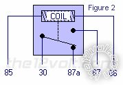
do i need a relay connected to get the remote start to work? if so how do i connect it with the right wiring? i do have a relay in hand and it looks exactly like this one... (below) which wire goes to which number?
viper 5902, 98 honda civic ex -- posted image.
P.S. a 1998 honda civic only has one accessory wire from the ignition if that helps
1998 Honda civic wiring diagram
https://www.the12volt.com/installbay/alarmdetail/1051.html
t&t tech 
Platinum - Posts: 2,608
Platinum spacespace
Joined: October 05, 2008
Location: Trinidad and Tobago
Posted: February 24, 2011 at 5:11 PM / IP Logged  

Here we go

On the h harness u have the orange wire to ground you don't need that, disconnect and isolate, you have the WHITE/ blue hooked up incorrectly as well, this wire takes a pulse from an external source to remote start the vehicle, (such as a button), For the parking lights did you plug the fuse in at the top of the control module? You have to open the door at the top and fuse according to polarity. The rest isn't needed.

You really should test wires before you connect especially that tach wire, you could end up in problems if you don't, the brown brake wire should connect to the wire that gets twelve when the brake is depressed, BLACK/ white to ground, rest is not needed.

Your wiring is correct on the heavy harness, you do not need the pink/black, isolate this wire.

commit your way to jehovah and he will act in your behalf. psalms 37:5
bryanmc1988 
Member - Posts: 48
Member spacespace
Joined: February 24, 2011
Location: California, United States
Posted: February 24, 2011 at 6:39 PM / IP Logged  
can you label the wires for me like the h2/2 etc for example... not sure what ur talking about when saying blue wire ... loln and whats not needed and whats needed to be connected to what
bryanmc1988 
Member - Posts: 48
Member spacespace
Joined: February 24, 2011
Location: California, United States
Posted: February 25, 2011 at 1:48 AM / IP Logged  
ok i have hooked up all the wires to the car and everything seems to work besides the violet h3/4 wire... when trying to start the car with a key, h3/4 does not get power from h3/5 but h3/5 does get power just not sending it to the h3/4 wire... any fix for this or is it a bad brain?
howie ll 
Pot Metal - Posts: 16,466
Pot Metal spacespace
Joined: January 09, 2007
Location: United Kingdom
Posted: February 25, 2011 at 4:01 AM / IP Logged  
Rejoin the BLACK/ white starter wire and just join the violet H3/4.
If the car now starts on the key you have a faulty internal starter/cut-anti/grind relay, change the brain. I'm amazed you've achieved so much with reference to my bye-line, i.e. assuming and not testing.
bryanmc1988 
Member - Posts: 48
Member spacespace
Joined: February 24, 2011
Location: California, United States
Posted: February 25, 2011 at 11:56 AM / IP Logged  
what do you mean? just connect the BLACK/ white wire's from the starter that i cut in half together and also keep the violet and green wire together with the starter wire(BLACK/ white), i know that when i plug in the starter wires together that the key will start up the car...
so could it be the brain?
howie ll 
Pot Metal - Posts: 16,466
Pot Metal spacespace
Joined: January 09, 2007
Location: United Kingdom
Posted: February 25, 2011 at 12:52 PM / IP Logged  
Then you've answered your own question, faulty internal relay either change the brain or rig an external relay;
Orange GWA to 85,ignition from pink to 86, key side starter to 87a, starter side from 30, violet from R/S to 87.
bryanmc1988 
Member - Posts: 48
Member spacespace
Joined: February 24, 2011
Location: California, United States
Posted: February 25, 2011 at 1:06 PM / IP Logged  
so where does the wires go to if i use a relay?
85 -whats orange "gwa" what wire is this? and from the car or the harness and if harness what wire?
86 - ignition from pink? from my harness h3/1 wire to 86?
87 - violet from h3/4 wire on harness to 87?
87a - BLACK/ white starter wire from my car to 87a on the relay?
30 - starter side on the car BLACK/ white wire to relay 30?
bryanmc1988 
Member - Posts: 48
Member spacespace
Joined: February 24, 2011
Location: California, United States
Posted: February 25, 2011 at 1:52 PM / IP Logged  
or could it be that i dont have a accessory 2 in my ignition and thats why there is no power? and a relay is needed... could that be the case
howie ll 
Pot Metal - Posts: 16,466
Pot Metal spacespace
Joined: January 09, 2007
Location: United Kingdom
Posted: February 25, 2011 at 2:12 PM / IP Logged  
Orange is your H1/12 it was in your first post, yes to all the other relay questions.
The pink/white in your last post is to be connected to your second accessory wire and programmed as such. This runs things like wipers etc.
Absolutely nothing to do with starting the car.
Page of 7

  Printable version Printable version Post ReplyPost New Topic
You cannot post new topics in this forum
You cannot reply to topics in this forum
You cannot delete your posts in this forum
You cannot edit your posts in this forum
You cannot create polls in this forum
You cannot vote in polls in this forum

  •  
Search the12volt.com
Follow the12volt.com Follow the12volt.com on Facebook
Sunday, May 5, 2024 • Copyright © 1999-2024 the12volt.com, All Rights Reserved Privacy Policy & Use of Cookies
Disclaimer: *All information on this site ( the12volt.com ) is provided "as is" without any warranty of any kind, either expressed or implied, including but not limited to fitness for a particular use. Any user assumes the entire risk as to the accuracy and use of this information. Please verify all wire colors and diagrams before applying any information.

Secured by Sectigo
the12volt.com spacer
Support the12volt.com
Top
the12volt.com spacer