the12volt.com spacer
icon

keyless entry issue 03 suburban


Post ReplyPost New Topic
< Prev Topic Next Topic >
ocallagdan3 
Member - Posts: 4
Member spacespace
Joined: October 11, 2011
Posted: October 11, 2011 at 10:26 PM / IP Logged  
Hello and thank you in advance for any assistance you can offer.
I'm afraid I'm in over my head and need some help finishing my install of a Remote Starter with keyless entry on my wife's Suburban.
Vehicle: 2003 Chevrolet Suburban Z71
Installing: Valiant RS160 Remote Starter with a Valiant Transponder Bypass Kit.
http://www.jcwhitney.com/rs160-remote-starter/p2020143.jcwx?filterid=j1
When I began my installation I didn't realize that I needed an interface module for the locks, so I had planned on bypassing the computer and just connecting directly to the power lock motor.
I have successfully installed the remote start and bypass modules so that the car will remote start properly. Also I have the keyless entry feature working correctly on the rear doors. I cannot puzzle out how to properly connect the keyless entry to the driver and passenger front doors. I have been using a DirectWire diagram for most of the install. According to DirectWire the grey and tan wires (pin 21 & 20) in the driver door module should interface directly with the power lock motor.
I have tried connecting the lock and unlock wires from my remote start directly to the grey and tan wires and that has had 0 effect. The instructions say to "use all wires and diode isolate" but I'm not sure how to accomplish this as I have 0 experience with diodes (I did try to read up on diode isolation, but I'm still not clear on how to do it in this situation).
My experience with auto electronics prior to this consists of 7 radio and speaker installs and 1 cruise control system on pre-1995 vehicles and a remote start on an 02 Silverado (that one went a lot smoother...).
If someone could please explain to me how to make this work, or better yet provide a picture(s) it would be greatly appreciated.
Thanks
-Dan
ocallagdan3 
Member - Posts: 4
Member spacespace
Joined: October 11, 2011
Posted: October 11, 2011 at 10:29 PM / IP Logged  
I think this picture from mobileinformationlabs.com is telling me what to do, but I'm not sure exactly how to do it.
keyless entry issue 03 suburban -- posted image.
kreg357 
Platinum - Posts: 7,783
Platinum spaceThis member has made a donation to the12volt.com. Click here for more info.spaceThis member has been recognized as an authority in Electrical Theory. Click here for more info.spaceThis member has been recognized as an authority in Mobile Security and Convenience. Click here for more info.spacespace
Joined: January 30, 2009
Location: Pennsylvania, United States
Posted: October 12, 2011 at 8:32 AM / IP Logged  

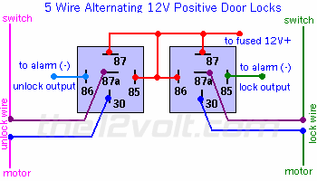
While the rear door locks are Type B (-), the front doors are 5 wire (rev) at the switch inside the doors.  You can not connect the (-) output from the R/S directly to these wies.  Here is a link to the 5 Wire (rev) wiring  :  https://www.the12volt.com/doorlocks/page3.asp#5w  This would have to done inside each door.  You could use two DEI 451M modules instead of making up your own relays and fuses.  Here is a link to the 451M install guide  :  https://www.the12volt.com/installbay/file.asp?ID=725

Another, easier, way is with the DEI MultiDL module.  It does all doors via a connection to an OBD2 diagnostic connector wire.  Here is a link to the MultiDL info  :  http://www.xpresskit.com/product.aspx?productid=188  While it has been discontinued, they are still available at various "online" sites.

Soldering is fun!
ocallagdan3 
Member - Posts: 4
Member spacespace
Joined: October 11, 2011
Posted: October 12, 2011 at 8:27 PM / IP Logged  
Thank you for your help, but I'm still in the same place.
If possible, lets pretend I'm retarded. (Not a big stretch)
So you're saying the picture I linked has nothing to do with what I'm trying to accomplish? Or it just wont work?
I have a limited amount of electrical experience, but its almost all [connect wire A to Wire B] stuff.
I looked at this before I posted.
keyless entry issue 03 suburban -- posted image.
Still makes no sense to me. Lots of colors and numbers... oooh, pretty.
Can I get a more idiot-proof explanation? Sorry to be a nuisance, if I'm hopeless just say so.
kreg357 
Platinum - Posts: 7,783
Platinum spaceThis member has made a donation to the12volt.com. Click here for more info.spaceThis member has been recognized as an authority in Electrical Theory. Click here for more info.spaceThis member has been recognized as an authority in Mobile Security and Convenience. Click here for more info.spacespace
Joined: January 30, 2009
Location: Pennsylvania, United States
Posted: October 12, 2011 at 9:48 PM / IP Logged  

The linked picture with the diodes would allow the (-) Lock and Unlock outputs from the RS160 to

perform a Lock / Arm and an Unlock / Disarm operation via the RS160's single Lock or Unlock
output, without affecting the vehicles normal circuitry or operation.  ( The Lock output is split
via the diodes and then connected to the vehicles individual lock and arm wires, etc.)  This would
work on some vehicles, but not yours.

Your truck is a bit of a hybrid.  The rear door locks are wired / controlled as Type B (-) signals

from the BCM while the front door locks are the Type C (rev) setup.  Why GM designed it that way
is anyone's guess.

The full detailed explanation would be rather involved.  It would include blocking diodes,

basic Single Pole Double Throw relay operation, door lock solenoid control / operation, polarity
conversion, remote starter programming / limitations and current handling / fusing requirements
among other items.  The Type C (rev) wiring is necessary because you are controlling the lock
and unlock functions of the each doors' lock solenoid directly. 

Here is a link to DEI Tech Tip 1601 :  https://www.the12volt.com/installbay/file.asp?ID=828

It has a short explanation of the trucks lock circuits and shows the relays, diodes and wiring
necessary using (+) Lock / Unlock outputs from the after-market brain.  As mentioned before, the
DEI 451M module can replace some of the relays.  Rather than use 6 relays, 4 fuses, 8 diodes and
open up the front doors, IMHO, the MultiDL module will save time and provide better reliability. 

Soldering is fun!
ocallagdan3 
Member - Posts: 4
Member spacespace
Joined: October 11, 2011
Posted: October 13, 2011 at 6:09 PM / IP Logged  
Ok. so you're saying I should buy the MultiDM, but I'm having no luck finding it online.
I can get the DEI 451M, and it probably sounds like a good idea since making my own relays is unlikely. I need two DEI 451Ms right? One each for the driver and passenger doors?
Then the colors/numbers should line up with the 5wire diagram posted above if I understand correctly?
I really appreciate the help kreg. You are making my wife a happy woman. I might owe you a beer.
kreg357 
Platinum - Posts: 7,783
Platinum spaceThis member has made a donation to the12volt.com. Click here for more info.spaceThis member has been recognized as an authority in Electrical Theory. Click here for more info.spaceThis member has been recognized as an authority in Mobile Security and Convenience. Click here for more info.spacespace
Joined: January 30, 2009
Location: Pennsylvania, United States
Posted: October 13, 2011 at 7:51 PM / IP Logged  
PM with info sent....keyless entry issue 03 suburban -- posted image.
Soldering is fun!

Sorry, you can NOT post a reply.
This topic is closed.

  Printable version Printable version Post ReplyPost New Topic
You cannot post new topics in this forum
You cannot reply to topics in this forum
You cannot delete your posts in this forum
You cannot edit your posts in this forum
You cannot create polls in this forum
You cannot vote in polls in this forum

  •  
Search the12volt.com
Follow the12volt.com Follow the12volt.com on Facebook
Saturday, April 27, 2024 • Copyright © 1999-2024 the12volt.com, All Rights Reserved Privacy Policy & Use of Cookies
Disclaimer: *All information on this site ( the12volt.com ) is provided "as is" without any warranty of any kind, either expressed or implied, including but not limited to fitness for a particular use. Any user assumes the entire risk as to the accuracy and use of this information. Please verify all wire colors and diagrams before applying any information.

Secured by Sectigo
the12volt.com spacer
Support the12volt.com
Top
the12volt.com spacer