the12volt.com spacer
icon

alarm/remote start, 06 subaru legacy gt


Post ReplyPost New Topic
< Prev Topic Next Topic >
dandude 
Member - Posts: 8
Member spacespace
Joined: January 24, 2012
Location: Arkansas, United States
Posted: January 27, 2012 at 3:40 PM / IP Logged  
I have been unable to find a wiring diagram which reflects my color codes and locations to make connections for remote start and key bypass modules. Have found several schematics but only some wiring locations and color codes agree with my vehicle. As a retired EE, I am about to give up on being able to make this install. Any help will be appreciated. I have the factory service manual with wiring and this doesn't even agree with my vehicle in some connections, particularly those to and from the ECM connectors. BTW, I am attempting to install a C3-601 (Autopage) remote start with a DEI 556UW bypass module.
Danny
flobee4 
Silver - Posts: 585
Silver spacespace
Joined: January 02, 2004
Location: United States
Posted: January 27, 2012 at 8:04 PM / IP Logged  
I did a 09 which should be the same:
Dash Comes apart pretty easy, But the steering Column Shroud needs some care. The bottom half comes off easy enough by unscrewing the visible screws, but the top half is screwed in also. There are 3 screws holding the top half in and are only accessible after you remove the bottom shroud. You shouldn't need to remove it, but if you do, make sure you find the 3 screws before trying to pull it up and off.
Ignition wires:
12volts - white
starter - WHITE/ black
ignition1 - green
ignition 2 - blue
accessory - yellow
Also at the steering column:
Positive Parking Lights - Orange in a 4 pin connector near the steering wheel on the bottom. It only had 3 wires in it, the other 2 were white.
You'll want to use positive parking lights as the negative parking lights do not work with the ignition off. So when you use your keyless entry, the parking lights won't flash.
You also don't need the keysense wire that is listed on some wiring charts.
At the brake switch is the brake wire - BROWN / white
at the BCM all in the same plug is:
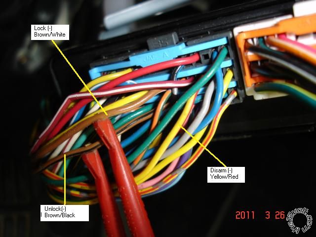
door lock - BROWN / white(-) test by pressing the drivers door panel door lock switch
door unlock -BROWN / black (-) test by pressing the drivers door panel door lock switch
disarm - Yellow/red (-) test by turning the key in the door lock cylinder on the outside of the drivers door.
Trunk release - WHITE/ black (you need to use a relay and cut the wire and "5-wire" it) test by pressing the trunk release button on the keyless remote.
When prewiring the remote start, I would use 2 diodes to split your trunk release output. One output would goto the disarm wire and then the other would goto the relay. This way when you are popping the trunk, the alarm won't go off.
dandude 
Member - Posts: 8
Member spacespace
Joined: January 24, 2012
Location: Arkansas, United States
Posted: January 27, 2012 at 8:36 PM / IP Logged  
Hi and thanks for the quick comments.
I obtained access to under the panel and steering column without any problems. I don't plan to parallel the door functions so my install will be less involved. I do need to locate and connect to the neutral switch was supposed to be the ECM WHITE/ green plug on pin # 31, a purple wire which seems not to be connected to the switch. You info on the parking lights was new to me and most helpful. The key sense wire is another which I did not find where it was supposed to be and possibly it is a BLACK/ white wire in the ign harness.
I will take a look at the 2009 connection assist wiring info available and see if this can be of help .
Thanks again,
Danny
kreg357 
Platinum - Posts: 7,787
Platinum spaceThis member has made a donation to the12volt.com. Click here for more info.spaceThis member has been recognized as an authority in Electrical Theory. Click here for more info.spaceThis member has been recognized as an authority in Mobile Security and Convenience. Click here for more info.spacespace
Joined: January 30, 2009
Location: Pennsylvania, United States
Posted: January 27, 2012 at 9:04 PM / IP Logged  

Here is a photo of the BIU with the lock wires marked  :

alarm/remote start, 06 subaru legacy gt -- posted image.

Soldering is fun!
offroadzj 
Gold - Posts: 2,043
Gold spaceThis member has made a donation to the12volt.com. Click here for more info.spaceThis member has been recognized as an authority in Mobile Security and Convenience. Click here for more info.spacespace
Joined: June 03, 2005
Location: New York, United States
Posted: January 27, 2012 at 10:08 PM / IP Logged  
Is this an automatic or standard transmission vehicle?
Kenny
Owner / Technician
KKD Garage LLC
Albany, NY 12205
dandude 
Member - Posts: 8
Member spacespace
Joined: January 24, 2012
Location: Arkansas, United States
Posted: January 28, 2012 at 8:06 AM / IP Logged  
Hi; Thanks for the question. It has a factory equipped automatic and it is a Legacy GT with standard 4 cyl turbo engine. It is equipped with the factory installed remote door lock and alarm system. I do not plan to incorporate these existing functions into my install of the remote start which will have it's own separate remote fob. The vin # 4S3BL676864200641.
offroadzj 
Gold - Posts: 2,043
Gold spaceThis member has made a donation to the12volt.com. Click here for more info.spaceThis member has been recognized as an authority in Mobile Security and Convenience. Click here for more info.spacespace
Joined: June 03, 2005
Location: New York, United States
Posted: January 28, 2012 at 12:11 PM / IP Logged  
If its an automatic then all you need to do with the neutral safety switch is either ground it or ground it through a toggle switch if you wish to have a means to prevent the remote starter from functioning (for working on the car, etc)
Kenny
Owner / Technician
KKD Garage LLC
Albany, NY 12205
dandude 
Member - Posts: 8
Member spacespace
Joined: January 24, 2012
Location: Arkansas, United States
Posted: January 28, 2012 at 2:56 PM / IP Logged  
Thanks, this is also helpful but still indicates the shortage of info for this particular car and installation.
I am still missing valid info on the plug and pin # or wire color and location to obtain the tach signal needed for the RS-601 starter module. Might you know this one too?
Thanks again.
Daniel
dandude 
Member - Posts: 8
Member spacespace
Joined: January 24, 2012
Location: Arkansas, United States
Posted: January 28, 2012 at 3:03 PM / IP Logged  
I appreciate your posted reply with nice photo. However you show function connections which I won't be using due to my retaining these functions on my factory installed remote.
Refer to my other posts regarding details on where I stand now which is primarily the location of where to connect to obtain the tach signal. Any help on this one?
Thanks, Daniel
kreg357 
Platinum - Posts: 7,787
Platinum spaceThis member has made a donation to the12volt.com. Click here for more info.spaceThis member has been recognized as an authority in Electrical Theory. Click here for more info.spaceThis member has been recognized as an authority in Mobile Security and Convenience. Click here for more info.spacespace
Joined: January 30, 2009
Location: Pennsylvania, United States
Posted: January 28, 2012 at 4:49 PM / IP Logged  

Here is the info from DEI.

Tachometer    pink to RED / White  (AC)      @ ECM, 35 pin plug, pin 22 or cluster
The ECM is behind the glove box.
On the 4 cylinder turbo models, the tach wire is in the 34 pin plug, pin 23.
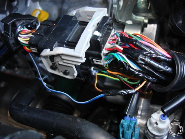
Can also go to a fuel injector under the hood and use the wire that is NOT blue/black (4 cyl),
red (4 cyl turbo), or yellow/blue (6 cyl).

I usually just go to a F.I., determine the non-common color and tap into it at

the connector pictured below. ( 2010 Forester non-turbo )

alarm/remote start, 06 subaru legacy gt -- posted image.

Soldering is fun!
Page of 2

  Printable version Printable version Post ReplyPost New Topic
You cannot post new topics in this forum
You cannot reply to topics in this forum
You cannot delete your posts in this forum
You cannot edit your posts in this forum
You cannot create polls in this forum
You cannot vote in polls in this forum

  •  
Search the12volt.com
Follow the12volt.com Follow the12volt.com on Facebook
Tuesday, May 14, 2024 • Copyright © 1999-2024 the12volt.com, All Rights Reserved Privacy Policy & Use of Cookies
Disclaimer: *All information on this site ( the12volt.com ) is provided "as is" without any warranty of any kind, either expressed or implied, including but not limited to fitness for a particular use. Any user assumes the entire risk as to the accuracy and use of this information. Please verify all wire colors and diagrams before applying any information.

Secured by Sectigo
the12volt.com spacer
Support the12volt.com
Top
the12volt.com spacer