the12volt.com spacer
icon

93 dodge cummins remote start


Post ReplyPost New Topic
< Prev Topic Next Topic >
tlane3546 
Member - Posts: 15
Member spacespace
Joined: November 16, 2013
Location: Indiana, United States
Posted: November 16, 2013 at 9:14 PM / IP Logged  
Hello everyone. I'm new to the forum and new to installing remote start on vehicles. I'm pretty proficient in wiring and reading schematics so this shouldnt be an issue, however, I have a 5101 Viper remote start and I want to pair it with my 93 Dodge D250 Cummins Turbo Diesel. I have all of the Dodges wiring diagrams and the Viper install sheet. I'm just confused on what wires in the remote start harness i dont need and exactly what ones need to be hooked up and to where. I have power door locks that I'd like to have wired to the Viper system as well. Any help or information is greatly appreciated. Thank you in advance,
Travis Lane
1
tlane3546 
Member - Posts: 15
Member spacespace
Joined: November 16, 2013
Location: Indiana, United States
Posted: November 17, 2013 at 6:54 PM / IP Logged  
Anyone? I can provide the Viper Install sheet if it would help?
1
kreg357 
Platinum - Posts: 7,783
Platinum spaceThis member has made a donation to the12volt.com. Click here for more info.spaceThis member has been recognized as an authority in Electrical Theory. Click here for more info.spaceThis member has been recognized as an authority in Mobile Security and Convenience. Click here for more info.spacespace
Joined: January 30, 2009
Location: Pennsylvania, United States
Posted: November 17, 2013 at 7:46 PM / IP Logged  

I will give it a go.  But there are some variations on the Viper models and their harnesses.  I'm not positive I have the

correct listing for your truck.  I assuming a D250 is a rear wheel drive ( 4X2 ) Ram pickup ( as opposed to the W series
4X4's ).  Obviously, you will want to verify all this info with a DMM.

H1/1  RED / WHITE  (-) 200mA TRUNK RELEASE OUTPUT Not used

H1/2  RED  (+)12v CONSTANT INPUT         Pink @ ignition switch harness
H1/3  BROWN  (-) HORN OUTPUT BLACK/ RED (-)  @ STEERING COLUMN HARNESS 
H1/4  WHITE/ BROWN  LIGHT FLASH ISOLATION WIRE   Not used
H1/5  BLACK  (-) CHASSIS GROUND          Chassis Ground
H1/6  VIOLET  (+) DOOR TRIGGER INPUT* Not used         
H1/7  BLUE  (-) FACTORY HORN INPUT** BLACK/ RED (-)  @ STEERING COLUMN HARNESS 
H1/8  GREEN  (-) DOOR TRIGGER INPUT* YELLOW (-)  @ DRIVERS DOOR PIN SWITCH 
H1/9  BLACK/ WHITE  (-) 200mA DOME LIGHT OUTPUT   YELLOW (-)  @ DRIVERS DOOR PIN SWITCH 
H1/10  WHITE/ BLUE  (-) REMOTE START/ TURBO TIMER ACT      Not used
H1/11  WHITE   PARKING LIGHT OUTPUT      **set Viper for (+)   BLACK / YELLOW (+)  @ 18 Pin BLUE Plug, at FIREWALL  or @ Headlight switch
H1/12  ORANGE  (-) 500mA GROUND WHEN ARMED OUTPUT Not used

H2/1  LIGHT GREEN/ BLACK  (-) 200mA FACTORY ALARM DISARM       Not used

H2/2  LIGHT GREEN / WHITE  (-) 200mA FACTORY ALARM ARM Not used
H2/3  WHITE/ VIOLET  (-) 200mA AUX 1 OUTPUT   Not used
H2/4  VIOLET/BLACK  (-) 200mA AUX 2 OUTPUT  Not used
H2/5  WHITE/ BLACK  (-) 200mA AUX 3 OUTPUT    Not used
H2/6  LIGHT BLUE  (-) 200mA 2ND UNLOCK OUTPUT     Not used
H2/7  GRAY/BLACK  (-) DIESEL WAIT TO START INPUT   Not used  *** use fixed 15 second delay

H3/1  PINK  IGNITION 1 INPUT/OUTPUT DARK BLUE (+)  @ IGNITION SWITCH HARNESS          

H3/2  RED / WHITE  (+) FUSED (30A) IGNITION 2           Red @ IGNITION SWITCH HARNESS
H3/3  ORANGE  ACCESSORY OUTPUT   BLACK/ ORANGE (+)  @ IGNITION SWITCH HARNESS 
H3/4  VIOLET  STARTER OUTPUT         YELLOW (+)  @ IGNITION SWITCH HARNESS 
H3/5  RED  (+) FUSED (30A) IGNITION 1 INPUT           Red @ IGNITION SWITCH HARNESS   
H3/6  PINK/WHITE  IGNITION 2 / FLEX RELAY OUTPUT 30     BLACK/ WHITE (+)  @ IGNITION SWITCH HARNESS
H3/7  PINK/BLACK  FLEX RELAY INPUT 87A key side   Not used
H3/8  RED / BLACK  (+) FUSED (30A) ACCESSORY/STARTER   Pink @ IGNITION SWITCH HARNESS

1  BLACK/ WHITE  (-) NEUTRAL SAFETY SWITCH INPUT        Chassis ground if auto trans

2  VIOLET/WHITE  TACHOMETER INPUT         ???  Don't see any diesel listings
3  BROWN  (+) BRAKE SHUTDOWN INPUT     BROWN / RED or WHITE/ TAN (+)  @ SWITCH ABOVE BRAKE PEDAL
4  GRAY  N/O or N/C (-) HOOD PIN SWITCH INPUT     Viper supplied hood pin switch
5  BLUE/WHITE  (-) 200 mA 2ND STATUS/REAR DEFOG       Not used

1  PINK/WHITE  (-) 200mA FLEX RELAY CONTROL OUTPUT   Not used

2  ORANGE  (-) 200mA ACCESSORY OUTPUT   Not used
3  VIOLET  (-) 200mA STARTER OUTPUT         Not used
4  PINK  (-) 200mA IGNITION 1 OUTPUT           Not used
5  BLUE  (-) 200mA STATUS OUTPUT  Not used

1  BLUE  (+) LOCK (-) UNLOCK OUTPUT       Use a Direct 451M door lock module or

2  EMPTY  NOT USED  use relays and follow this Type C (rev) diagram :
3  GREEN  (-) LOCK (+) UNLOCK OUTPUT    https://www.the12volt.com/doorlocks/page3.asp#5w
Lock wire info :
POWER LOCK          ORANGE / VIOLET (TYPE C)      BEHIND GLOVEBOX, BLACK Plug   or DKP
POWER UNLOCK     PINK/VIOLET (TYPE C) BEHIND GLOVEBOX, BLACK Plug   or DKP

Soldering is fun!
tlane3546 
Member - Posts: 15
Member spacespace
Joined: November 16, 2013
Location: Indiana, United States
Posted: November 17, 2013 at 8:12 PM / IP Logged  
This is precisely what i was looking for. Thank you so much. I have the diesel tach provision wire, Grey/Light Blue. and yes the D250 Ram is just a 2WD and the W250 is the 4x4.
Let me ask this, the harnesses that have no wires to hook to, do i still have to plug those into the remote start module? Its a dumb question I know. And I'm sure i know the answer to it already.
1
kreg357 
Platinum - Posts: 7,783
Platinum spaceThis member has made a donation to the12volt.com. Click here for more info.spaceThis member has been recognized as an authority in Electrical Theory. Click here for more info.spaceThis member has been recognized as an authority in Mobile Security and Convenience. Click here for more info.spacespace
Joined: January 30, 2009
Location: Pennsylvania, United States
Posted: November 17, 2013 at 8:44 PM / IP Logged  

Used to have a 1977 W150 Power Wagon.  93 dodge cummins remote start -- posted image.

No such thing as a dumb question.  93 dodge cummins remote start -- posted image.  Yes, if a harness has no needed wires, leave it off.  Unused wires in a harness can be cut to 2" and bundled neatly or even de-pinned / removed.  Keeping the install neat is important.

Do you have any info on a Wait-To-Start wire?  That could work better than a fixed 15 second delay.

Soldering is fun!
tlane3546 
Member - Posts: 15
Member spacespace
Joined: November 16, 2013
Location: Indiana, United States
Posted: November 18, 2013 at 5:03 AM / IP Logged  
Yes i do, the wait-to-start wire is Dark GREEN / WHITE. DO i just hook the Grey/Black directly to this wire? It says something about a resistor in the install sheet that came with
1
kreg357 
Platinum - Posts: 7,783
Platinum spaceThis member has made a donation to the12volt.com. Click here for more info.spaceThis member has been recognized as an authority in Electrical Theory. Click here for more info.spaceThis member has been recognized as an authority in Mobile Security and Convenience. Click here for more info.spacespace
Joined: January 30, 2009
Location: Pennsylvania, United States
Posted: November 18, 2013 at 6:05 AM / IP Logged  
The Viper is looking for a (-) input signal on it's WTS wire.  Depending on the vehicle brand ( Ford, Dodge, GM ) and the engine, the WTS signal type varies.  Sometimes a diode is also necessary.  Follow the install sheet, but if it does work properly you can always use a fixed time delay. 
Soldering is fun!
tlane3546 
Member - Posts: 15
Member spacespace
Joined: November 16, 2013
Location: Indiana, United States
Posted: November 18, 2013 at 8:23 PM / IP Logged  
Excellent, thank you for all your help. I will be tackling this this weekend. I appreciate everything and I'll let you know how it goes.
1
tlane3546 
Member - Posts: 15
Member spacespace
Joined: November 16, 2013
Location: Indiana, United States
Posted: November 18, 2013 at 8:42 PM / IP Logged  
93 dodge cummins remote start -- posted image.
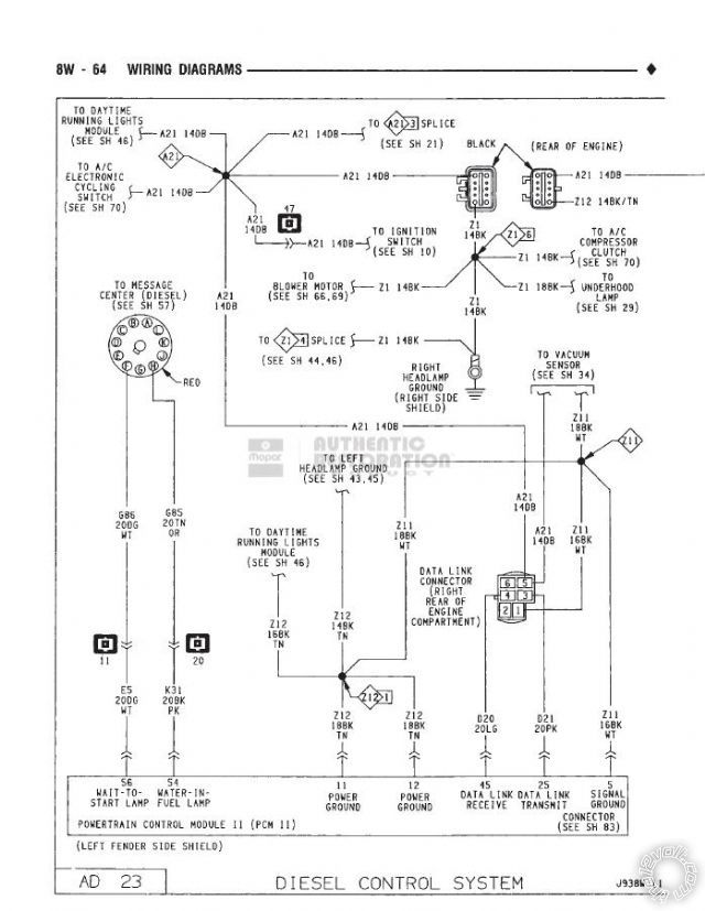
here is the schematic of the wait to start circuit. I'm not sure if its positive or negative?
1
kreg357 
Platinum - Posts: 7,783
Platinum spaceThis member has made a donation to the12volt.com. Click here for more info.spaceThis member has been recognized as an authority in Electrical Theory. Click here for more info.spaceThis member has been recognized as an authority in Mobile Security and Convenience. Click here for more info.spacespace
Joined: January 30, 2009
Location: Pennsylvania, United States
Posted: November 18, 2013 at 9:35 PM / IP Logged  
Can't tell from the diagram.  The sure way would be to put a DMM on the wire and see what happens during a start-up.  Maybe another forum member has prior experience with this model truck and can help out.
Soldering is fun!
Page of 3

  Printable version Printable version Post ReplyPost New Topic
You cannot post new topics in this forum
You cannot reply to topics in this forum
You cannot delete your posts in this forum
You cannot edit your posts in this forum
You cannot create polls in this forum
You cannot vote in polls in this forum

  •  
Search the12volt.com
Follow the12volt.com Follow the12volt.com on Facebook
Sunday, April 28, 2024 • Copyright © 1999-2024 the12volt.com, All Rights Reserved Privacy Policy & Use of Cookies
Disclaimer: *All information on this site ( the12volt.com ) is provided "as is" without any warranty of any kind, either expressed or implied, including but not limited to fitness for a particular use. Any user assumes the entire risk as to the accuracy and use of this information. Please verify all wire colors and diagrams before applying any information.

Secured by Sectigo
the12volt.com spacer
Support the12volt.com
Top
the12volt.com spacer