OK. I like your through preliminary work on this project. It truely is "all in the planning".
The CM6200 and Blade AL is a great combination. Very compact and reliable. The Blade AL needs to flashed with the DL TL1
firmware while inserted into the CM6200. This requires the ADS USB cable and access to the Flash section of their WEB site.
When you do this, it will also update the firmware on the CM6200 ( if necessary ) and allow you to set the CM6200 programming
options.
For vehicle wiring, here are some sources :
Here is a link to Bulldog Security :
http://www.bulldogsecurity.com/bdnew/vehiclewiringdiagrams.aspHere is a link to Ready Remote :
http://www.readyremote.com/main.aspHere is a link to AudioVox :
http://techservices.audiovox.com/AccessRequest.aspx Sign-up & info is free.
Your next step is to download all the wire guide info you can from as many sources as possible. Compare them as there
probably will be differences. Consolidate everything on a cheat sheet. You will use this as your guide during the install.
The Blade w/TL1 will handle a bunch of things for you. They are listed on Page 2 of the install guide. The Type 1 Wiring Diagram
gives you most of the rest of the wiring. You car has a few exceptions in it.
You will notice that the wiring guides list two Starter wires, two Ignition wires and one Accessory wire at the main ignition switch
harness. You should power all these wires separately. The CM6200 only has one of each at the CN1 connector and an extra 30/40
Amp Bosch style relay, with harness, for one additional ignition circuit. You can use this for the Starter2 circuit and buy an additional
relay for the Ignition2 circuit. The control for these external relays will be the CN2 Pin 5 and Pin 7.
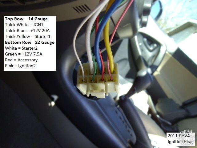
Pin 1 White (+) 12V Accessory white + ignition switch, white 8 pin plug, pin 2
Pin 2 Yellow (+) 12V Starter blue + ignition switch, white 8 pin plug, pin 7
Pin 3 Green #1 12V Ignition yellow + ignition switch, white 8 pin plug, pin 6
Pin 4 Black Ground (-) chassis ground
Pin 5 Red #1 12V Constant black (30A) + ignition switch, white 8 pin plug, pin 5
Pin 5 Red #2 12V Constant black (30A) + ignition switch, white 8 pin plug, pin 5
Pin 6 GREEN / WHITE Parking Light Output (+) Not Used
Pin 1 Blue Output to Starter Kill (-) Prewired to anti-grind/start-kill relay in CM6200 kit
Pin 2 ORANGE / Black Parking Light Reminder (-) Input Not used ( used w/manual trans )
Pin 3 GREEN / WHITE Parking Light Output (-) black (-) @ headlight switch, white 20 pin plug, pin 18
Pin 4 Light Blue E Brake Covered by BLADE-AL
Pin 5 RED / Black - 2nd Starter Output (-) Use with supplied extra relay for Starter2
Pin 6 Light Blue/White Brake 12V Input (+) Covered by BLADE-AL
Pin 7 Green 2nd Ignition Output (-) Used with additional relay for IGN2
Pin 8 Violet/Black Trunk Trigger Input (-) Covered by BLADE-AL
Pin 9 WHITE/ Black 2nd Accessory Output (-) not used
Pin 10 RED / White Door Trigger Input (+/-) Covered by BLADE-AL
Pin 11 Black Status/GWR Output (-) Covered by BLADE-AL
Pin 12 BROWN / White Key Sense/Glow Plug Not Used
Pin 13 Orange Rearm Output (-) Covered by BLADE-AL
Pin 14 Pink Slave/Closed Input (-) Not used
Pin 15 ORANGE / White Disarm Output (-) Covered by BLADE-AL
Pin 16 Yellow/Black Engine Sense/Tach Input Covered by BLADE-AL Do Tach Learn process
Pin 17 White Horn Output (-) white to black (-) @ horn switch Optional
Pin 18 Gray/Black Hood Pin Input (-) test for Factory Hood Pin
Pin 19 Violet Aux1 Output (-) Not Used
Pin 20 Brown 12V Siren Output (+) Not Used
Ignition2 relay wiring
Relay Pin 85 to CM6200 CN2, Pin 7, Green
Relay Pin 86 and 87 to Camry black (30A) (+) ignition switch, white 8 pin plug, pin 5
Relay Pin 30 to Camry IGN2, pink (+) ignition switch, white 8 pin plug, pin 1
Relay Pin 87a not used
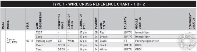
Here is a photo of the Headlight connector in the steering column of a 2011 RAV4 :
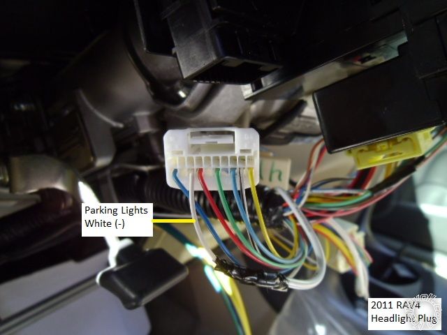
It is a White 20 Pin connector but the Parking Light wire at Pin 18 is White, your Camry's wire will be Black.
If you want photos of these wires, Fortin has a optional service called WireColor that should provide pictures of most
of these wires. They change a $5 per vehicle fee. Here is a link :
http://wirecolor.com/en/Soldering is fun!


 Topic Closed)


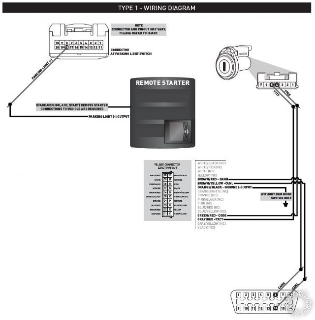 The connection information for the BLADE-AL wiring harness is stated as follows in the BLADE-AL manual. The information is listed in the order of: "BLADE PIN#-BLADE WIRE COLOR-ITEM-FACTORY CONNECTOR INFO-FACTORY PIN POSITION-FACTORY WIRE COLOR-LOCATION".
Pin 1 Gray/Red TXCT 7 Pin Connector Pin 5 Red Immobilizer (Ignition switch per diagram)
Pin 2 GREEN/ Red CODE 7 Pin Connector Pin 4 Brown Immobilizer (Ignition switch per diagram)
Pin 5 ORANGE / Black GROUND INPUT (-) Only if I don't use a Hood Pin
Pin 6 BROWN / Red CANH 16 Pin Connector Pin 6 Black OBDII
Pin 16 BROWN / Yellow CANL 16 Pin Connector Pin 14 White OBDII
Following is a picture of the wiring callout from the BLADE-AL manual.
The connection information for the BLADE-AL wiring harness is stated as follows in the BLADE-AL manual. The information is listed in the order of: "BLADE PIN#-BLADE WIRE COLOR-ITEM-FACTORY CONNECTOR INFO-FACTORY PIN POSITION-FACTORY WIRE COLOR-LOCATION".
Pin 1 Gray/Red TXCT 7 Pin Connector Pin 5 Red Immobilizer (Ignition switch per diagram)
Pin 2 GREEN/ Red CODE 7 Pin Connector Pin 4 Brown Immobilizer (Ignition switch per diagram)
Pin 5 ORANGE / Black GROUND INPUT (-) Only if I don't use a Hood Pin
Pin 6 BROWN / Red CANH 16 Pin Connector Pin 6 Black OBDII
Pin 16 BROWN / Yellow CANL 16 Pin Connector Pin 14 White OBDII
Following is a picture of the wiring callout from the BLADE-AL manual.
 My next questions are in regards to the actual CM6200 wiring. Following is a picture of the wiring requirements from the CM6200 manual:
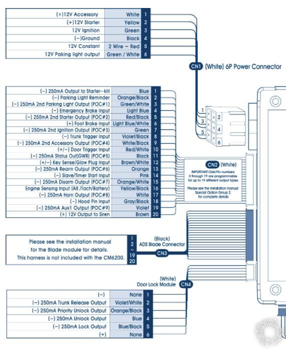 In regards to the CM6200 wiring diagram, following is my understanding of the additional wiring needed beyond the BLADE-AL wiring harness. My questions here have to do with getting direction on where to best find some of the factory wires to tie into and if I need the specific connection or not. Please feel free to correct the factory wire location listed below if I don't have it correct. The information is listed in order of "CM6200 CONNECTOR PIN#-WIRE COLOR-DESCRIPTION-LOCATION TO LAND WIRE (FACTORY WIRE COLOR-FACTORY PIN#)". I'll go over it for each connector:
CN1 (6P Power Connector):
Question #1: What color and pin is the starter wire coming from the factory ignition harness to tie into the starter relay?
Pin 1 White (+) 12V Accessory Ignition Harness (Wire Color? Pin?)
Pin 2 Yellow (+) 12V Starter Prewired to anti-grind/starter-kill relay in CM6200 kit
Pin 3 Green #1 12V Ignition Ignition Harness (Wire Color? Pin?)
Pin 3 Green #2 12V Ignition Prewired to anti-grind/starter-kill relay in CM6200 kit
Pin 4 Black Ground (-) Somewhere on firewall with a good ground
Pin 5 Red #1 12V Constant Location? Wire Color? Pin?
Pin 5 Red #2 12V Constant Location? Wire Color? Pin?
Pin 6 GREEN / WHITE Parking Light Output (+) Not Used based on BLADE-AL diagram stating I need to wire the Parking Light Output (-) for my vehicle.
CN2 (20P Input/Output Connector):
Question #2: Do I need to wire the "2nd Ignition/Starter/Accessory" relay harness if I'm not using it to power a secondary starter/ignition/accessory or is this optional?
Question #3: Where can I find the Parking Light Switch location or at least the location of the Parking Light Switch wire to tie into?
Pin 1 Blue Output to Starter Kill (-) Prewired to anti-grind/start-kill relay in CM6200 kit
Pin 2 ORANGE / Black Parking Light Reminder (-) Input Do I need this?
Pin 3 GREEN / WHITE Parking Light Output (-) Where is Parking Light Switch location?
Pin 4 Light Blue E Brake Covered by BLADE-AL
Pin 5 RED / Black - 2nd Starter Output (-) Do I need this?
Pin 6 Light Blue/White Brake 12V Input (+) Covered by BLADE-AL
Pin 7 Green 2nd Ignition Output (-) Do I need this?
Pin 8 Violet/Black Trunk Trigger Input (-) Covered by BLADE-AL
Pin 9 WHITE/ Black 2nd Accessory Output (-) Do I need this?
Pin 10 RED / White Door Trigger Input (+/-) Covered by BLADE-AL
Pin 11 Black Status/GWR Output (-) Covered by BLADE-AL
Pin 12 BROWN / White Key Sense/Glow Plug Do I need this?
Pin 13 Orange Rearm Output (-) Covered by BLADE-AL
Pin 14 Pink Slave/Closed Input (-) Do I need this?
Pin 15 ORANGE / White Disarm Output (-) Covered by BLADE-AL
Pin 16 Yellow/Black Engine Sense/Tach Input Covered by BLADE-AL
Pin 17 White Horn Output (-) Do I need this?
Pin 18 Gray/Black Hood Pin Input (-) Does my Camry have a factory Hood Pin? If not, I may install the Hood Pin that comes in the CM6200 kit. Otherwise I'll ground Pin 5 on the BLADE-AL harness.
Pin 19 Violet Aux1 Output (-) Do I need this?
Pin 20 Brown 12V Siren Output (+) Do I need this?
CN4 (6P Door Lock Module): My understanding is that all of these connections are covered by the BLADE-AL. Is this correct?
In regards to the CM6200 wiring diagram, following is my understanding of the additional wiring needed beyond the BLADE-AL wiring harness. My questions here have to do with getting direction on where to best find some of the factory wires to tie into and if I need the specific connection or not. Please feel free to correct the factory wire location listed below if I don't have it correct. The information is listed in order of "CM6200 CONNECTOR PIN#-WIRE COLOR-DESCRIPTION-LOCATION TO LAND WIRE (FACTORY WIRE COLOR-FACTORY PIN#)". I'll go over it for each connector:
CN1 (6P Power Connector):
Question #1: What color and pin is the starter wire coming from the factory ignition harness to tie into the starter relay?
Pin 1 White (+) 12V Accessory Ignition Harness (Wire Color? Pin?)
Pin 2 Yellow (+) 12V Starter Prewired to anti-grind/starter-kill relay in CM6200 kit
Pin 3 Green #1 12V Ignition Ignition Harness (Wire Color? Pin?)
Pin 3 Green #2 12V Ignition Prewired to anti-grind/starter-kill relay in CM6200 kit
Pin 4 Black Ground (-) Somewhere on firewall with a good ground
Pin 5 Red #1 12V Constant Location? Wire Color? Pin?
Pin 5 Red #2 12V Constant Location? Wire Color? Pin?
Pin 6 GREEN / WHITE Parking Light Output (+) Not Used based on BLADE-AL diagram stating I need to wire the Parking Light Output (-) for my vehicle.
CN2 (20P Input/Output Connector):
Question #2: Do I need to wire the "2nd Ignition/Starter/Accessory" relay harness if I'm not using it to power a secondary starter/ignition/accessory or is this optional?
Question #3: Where can I find the Parking Light Switch location or at least the location of the Parking Light Switch wire to tie into?
Pin 1 Blue Output to Starter Kill (-) Prewired to anti-grind/start-kill relay in CM6200 kit
Pin 2 ORANGE / Black Parking Light Reminder (-) Input Do I need this?
Pin 3 GREEN / WHITE Parking Light Output (-) Where is Parking Light Switch location?
Pin 4 Light Blue E Brake Covered by BLADE-AL
Pin 5 RED / Black - 2nd Starter Output (-) Do I need this?
Pin 6 Light Blue/White Brake 12V Input (+) Covered by BLADE-AL
Pin 7 Green 2nd Ignition Output (-) Do I need this?
Pin 8 Violet/Black Trunk Trigger Input (-) Covered by BLADE-AL
Pin 9 WHITE/ Black 2nd Accessory Output (-) Do I need this?
Pin 10 RED / White Door Trigger Input (+/-) Covered by BLADE-AL
Pin 11 Black Status/GWR Output (-) Covered by BLADE-AL
Pin 12 BROWN / White Key Sense/Glow Plug Do I need this?
Pin 13 Orange Rearm Output (-) Covered by BLADE-AL
Pin 14 Pink Slave/Closed Input (-) Do I need this?
Pin 15 ORANGE / White Disarm Output (-) Covered by BLADE-AL
Pin 16 Yellow/Black Engine Sense/Tach Input Covered by BLADE-AL
Pin 17 White Horn Output (-) Do I need this?
Pin 18 Gray/Black Hood Pin Input (-) Does my Camry have a factory Hood Pin? If not, I may install the Hood Pin that comes in the CM6200 kit. Otherwise I'll ground Pin 5 on the BLADE-AL harness.
Pin 19 Violet Aux1 Output (-) Do I need this?
Pin 20 Brown 12V Siren Output (+) Do I need this?
CN4 (6P Door Lock Module): My understanding is that all of these connections are covered by the BLADE-AL. Is this correct?


 Printable version


