the12volt.com spacer
icon

96 ford f150 keyless entry


Post ReplyPost New Topic
< Prev Topic Next Topic >
wes5314 
Member - Posts: 26
Member spacespace
Joined: June 26, 2004
Location: United States
Posted: March 11, 2016 at 6:49 PM / IP Logged Link to Post Post Reply Quote wes5314
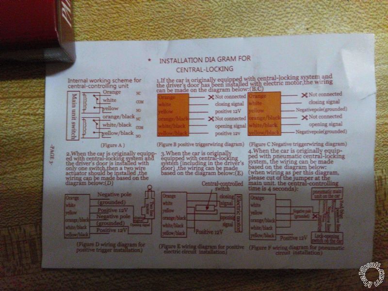
i have 96 ford f150 im trying to wire up they keyless entry to the door lock i have printed the diagram for the colors and such but the 5 wire door locks are confusing me the truck does not have the rke entry box so im using after market here is the diagram for the after market unit my intentions is to run everything thru the door jam and connect at kick panel 96 ford f150 keyless entry -- posted image.
wes5314
kreg357 
Platinum - Posts: 7,783
Platinum spaceThis member has made a donation to the12volt.com. Click here for more info.spaceThis member has been recognized as an authority in Electrical Theory. Click here for more info.spaceThis member has been recognized as an authority in Mobile Security and Convenience. Click here for more info.spacespace
Joined: January 30, 2009
Location: Pennsylvania, United States
Posted: March 12, 2016 at 7:39 AM / IP Logged Link to Post Post Reply Quote kreg357

Couldn't tell from your post but I'm assuming the F150 has factory power door locks but not the Factory Remote

Keyless Entry.  Here is the vehicle lock wiring info from this site :

Door Lock          Pink / YELLOW   Passenger's Kick,  w/o Keyless Reverse Polarity,  use Driver's Switch to Test 

Door Unlock       Pink/Light Green       Passenger's Kick,  w/o Keyless Reverse Polarity,  use Driver's Switch to Test 

This is somewhat similar to the Pictorial on the 2002- 2005 F250.  Here is a link : 

https://www.the12volt.com/installbay/forum_posts.asp?tid=133810

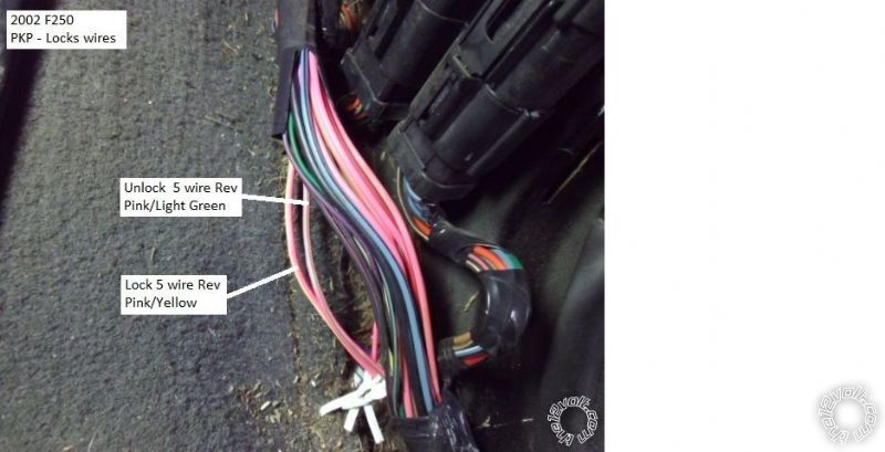
Here is a photo from that Pictorial of the lock wires in the PKP ( your truck might be similar ) :

96 ford f150 keyless entry -- posted image.

You will wire it it in the 5 wire Reverse mode using the two wires in the PKP.  Here is the wiring for your after-market

unit :

Lock portion :

Orange wire ( aka Pin 87a ) to switch side of cut Pink / YELLOW wire in PKP
White wire ( aka Pin 30 ) to motor side of cut Pink / YELLOW wire in PKP
Yellow wire ( aka Pin 87 ) to +12V constant through 15 Amp fuse ( combine with Yellow/Black wire )

Unlock portion :

ORANGE / Black wire ( aka Pin 87a ) to switch side of cut Pink/Lt. Green wire in PKP
WHITE/ Black wire ( aka Pin 30 ) to motor side of cut Pink/Lt. Green  in PKP
Yellow/Black wire ( aka Pin 87 ) to +12V constant through 15 Amp fuse ( combine with Yellow wire )

To determine which side of the cut wire is the switch side, connect a DMM to one side of the cut wire and press the drivers

door lock ( or unlock ) button.  If the DMM goes to +12V you have the switch side.

Soldering is fun!

If you wish to post a reply to this topic, you must first login.
If you are not already registered, you must first register.

  Printable version Printable version Post ReplyPost New Topic
You cannot post new topics in this forum
You cannot reply to topics in this forum
You cannot delete your posts in this forum
You cannot edit your posts in this forum
You cannot create polls in this forum
You cannot vote in polls in this forum

  •  
Search the12volt.com
Follow the12volt.com Follow the12volt.com on Facebook
Sunday, April 28, 2024 • Copyright © 1999-2024 the12volt.com, All Rights Reserved Privacy Policy & Use of Cookies
Disclaimer: *All information on this site ( the12volt.com ) is provided "as is" without any warranty of any kind, either expressed or implied, including but not limited to fitness for a particular use. Any user assumes the entire risk as to the accuracy and use of this information. Please verify all wire colors and diagrams before applying any information.

Secured by Sectigo
the12volt.com spacer
Support the12volt.com
Top
the12volt.com spacer