the12volt.com spacer
icon

2003 Nissan Altima Remote Start info


Post ReplyPost New Topic
< Prev Topic Next Topic >
ewibolo 
Member - Posts: 8
Member spacespace
Joined: November 05, 2016
Location: Florida, United States
Posted: November 05, 2016 at 10:35 PM / IP Logged Link to Post Post Reply Quote ewibolo
Hello Everyone, first post here. I am attempting a 1st install of a remote start system on my 2003 Nissan Altima ginuea pig with an Avital 4103 w/ a Dball2 bypass module.
I have installed quite a few car stereos, but nothing this "integrated". I have some questions before I get started, if y'all can help. Thanks in advance.
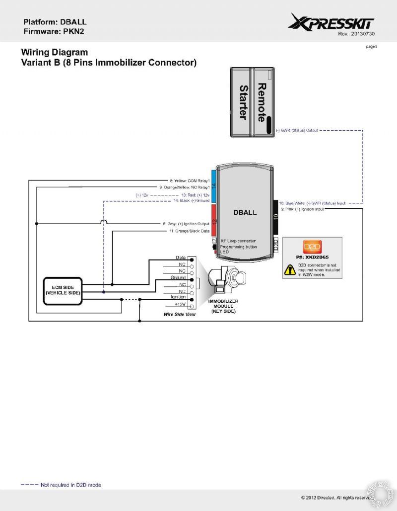
As far as wiring the Avital 4103 goes, i have the following wiring scheme as follows. Can someone please help me see if I have this right?
Primary harness (H1) wiring diagram
H1/1     LHT GRN/BLK FACTORY ALARM DISARM na
H1/2     GREEN / WHITE FACTORY REARM   na
H1/3     YELLOW (+) IGNITION OUT (TO ALARM) CONNECT TO PINK HEAVY GAGE HARNESS?
H1/4     WHITE/ BLUE (-) ACTIVATION INPUT   na
H1/5     ORANGE (-) GROUND WHEN LOCKED na
H1/6     BROWN (-) HORN OUTPUT   HORN
H1/7     RED / WHITE (-) TRUNK RELEASE OUTPUT TRUNK
H1/8     BLACK   GROUND        GROUND
H1/9     WHITE   (+/-) LIGHT FLASH   na
4-pin satellite harness diagram
1     BLUE   STATUS OUTPUT   na
2     ORANGE (-) ACCESSORY OUTPUT   na
3     PURPLE (-) STARTER OUTPUT   na     
4     PINK   (-) STARTER OUTPUT   na
Heavy gauge relay wiring diagram
1     PINK (+) (30 AMP) OUTPUT TO IGN CIRCUIT   1st ignition circuit
2     PURPLE (+) (30 AMP) OUTPUT TO STARTR CIRCUIT 1st starter circuit
3     ORANGE      (+) (30 AMP) OUTPUT TO ACCESS CIRCUIT 1st accessry circuit or NOT NECCESSRY?
4     RED (+) (30A) HIGH CURRENT 12 INPUT   Battery positive wire (green)
5     PINK/WHITE     (+) PROGRAMMABLE OUTPUT FOR ACCSS/IGN NOT NECCESSARY TO CONNECT?
6     RED (+) (30A) HIGH CURRENT 12V INPUT   Connect this to same battery
 positive wire as above?
Door lock harness, 3-pin connector
1     BLUE (-) UNLOCK OUTPUT   UNLOCK- DOOR PANEL
2     EMPTY NOT USED        na
3     GREEN (-) LOCK OUTPUT   LOCK - DOOR PANEL
Remote start harness (H2) wiring diagram
H2/1     BLACK/ WHITE (-) NEUTRAL SAFETY SWITCH INPUT CONNECT TO NEUTRAL SAFETY WIRE
 (GREEN/ RED) OR DIRECT TO GROUND
H2/2     VIOLET/WHITE TACHOMETER INPUT WIRE   na
H2/3     BROWN (+) BRAKE SWITCH SHUTDOWN WIRE BRAKE SWITCH AT BREAK PEDAL
H2/4     GRAY   (-) HOOD PINSWITCH SHUTDOWN WIRE na
H2/5     BLUE/WHITE (-) 200mA 2ND STATUS/REAR DEFOGGE na
kreg357 
Platinum - Posts: 7,783
Platinum spaceThis member has made a donation to the12volt.com. Click here for more info.spaceThis member has been recognized as an authority in Electrical Theory. Click here for more info.spaceThis member has been recognized as an authority in Mobile Security and Convenience. Click here for more info.spacespace
Joined: January 30, 2009
Location: Pennsylvania, United States
Posted: November 06, 2016 at 2:33 AM / IP Logged Link to Post Post Reply Quote kreg357
Heavy gauge relay wiring diagram
1     PINK        (+) (30 AMP) OUTPUT TO IGN CIRCUIT        1st ignition circuit BLACK/ RED (+)
2     PURPLE      (+) (30 AMP) OUTPUT TO STARTER CIRCUIT     1st starter circuit BLACK/ Red (+)
3     ORANGE      (+) (30 AMP) OUTPUT TO ACCESS CIRCUIT     1st accessroy circuit RED (+)
4     RED         (+) (30A) HIGH CURRENT 12 INPUT           Battery positive wire (green)
5     PINK/WHITE  (+) PROGRAMMABLE OUTPUT FOR ACCSS/IGN     2nd Accessory circuit WHITE/ BLUE (+) * program to ACC
6     RED         (+) (30A) HIGH CURRENT 12V INPUT          BatteryGREEN (+)
4-pin satellite harness diagram
1     BLUE        STATUS OUTPUT               na
2     ORANGE      (-) ACCESSORY OUTPUT        to extra 30/40 Amp SPDT Relay Pin 85
3     PURPLE      (-) STARTER OUTPUT          na     
4     PINK        (-) STARTER OUTPUT          na
Extra 30/40 Amp SPDT Relay w/harness and fuseholder with 20 amp fuse
Relay Pin 85 to 4103 PURPLE (-) STARTER OUTPUT  
Relay Pins 86 and 87 to Battery (+) through fuse
Relay Pin 30 to STARTER 2 BLACK / YELLOW (+)
Notice that there are two BLACK/ Red wires at the ignition switch harness. You must test to determine which is IGN1 and which is Starter1.
Soldering is fun!
kreg357 
Platinum - Posts: 7,783
Platinum spaceThis member has made a donation to the12volt.com. Click here for more info.spaceThis member has been recognized as an authority in Electrical Theory. Click here for more info.spaceThis member has been recognized as an authority in Mobile Security and Convenience. Click here for more info.spacespace
Joined: January 30, 2009
Location: Pennsylvania, United States
Posted: November 06, 2016 at 2:42 AM / IP Logged Link to Post Post Reply Quote kreg357
Primary harness (H1) wiring diagram
H1/1     LHT GRN/BLK    FACTORY ALARM DISARM          na
H1/2     GREEN / WHITE    FACTORY REARM                na
H1/3     YELLOW         (+) IGNITION OUT (TO ALARM)   na
H1/4     WHITE/ BLUE     (-) ACTIVATION INPUT          na
H1/5     ORANGE         (-) GROUND WHEN LOCKED        na
H1/6     BROWN          (-) HORN OUTPUT               HORN
H1/7     RED / WHITE      (-) TRUNK RELEASE OUTPUT     TRUNK
H1/8     BLACK          GROUND                        GROUND
H1/9     WHITE          (+/-) LIGHT FLASH *set to +   RED / BLUE (+) IN DRIVERS KICK PANEL, HARNESS to REAR of VEHICLE
Soldering is fun!
ewibolo 
Member - Posts: 8
Member spacespace
Joined: November 05, 2016
Location: Florida, United States
Posted: November 06, 2016 at 1:53 PM / IP Logged Link to Post Post Reply Quote ewibolo
Thanks for the guidance Kreg357, I have a couple more questions if you can.
1. Do both of the RED, 30a high current inputs go to same Green battery positive wire in ignition harness?
2. on the 4-pin satellite, the orange to spdt 30A relay pin 85, what is that for?
3. on the Relay wiring you indicate the orange accessory out from the satellite harness to pin 85 on relay, then also Relay Pin 85 to 4103 PURPLE (-) STARTER OUTPUT (on satellite harness also I believe).
This would mean there are 2 wires connected to pin 85- the 4103 purple starter out and the orange accessory out. I'm a little confused.
Thanks for your patience.
kreg357 wrote:
Primary harness (H1) wiring diagram
H1/1     LHT GRN/BLK    FACTORY ALARM DISARM na
H1/2     GREEN / WHITE    FACTORY REARM na
H1/3     YELLOW        (+) IGNITION OUT (TO ALARM)   na
H1/4     WHITE/ BLUE     (-) ACTIVATION INPUT na
H1/5     ORANGE        (-) GROUND WHEN LOCKED        na
H1/6     BROWN (-) HORN OUTPUTHORN
H1/7     RED / WHITE      (-) TRUNK RELEASE OUTPUT      TRUNK
H1/8     BLACK GROUND        GROUND
H1/9     WHITE (+/-) LIGHT FLASH *set to +   RED / BLUE (+) IN DRIVERS KICK PANEL, HARNESS to REAR of VEHICLE
kreg357 wrote:
Heavy gauge relay wiring diagram
1     PINK        (+) (30 AMP) OUTPUT TO IGN CIRCUIT        1st ignition circuit BLACK/ RED (+)
2     PURPLE      (+) (30 AMP) OUTPUT TO STARTER CIRCUIT     1st starter circuit BLACK/ Red (+)
3     ORANGE      (+) (30 AMP) OUTPUT TO ACCESS CIRCUIT     1st accessroy circuit RED (+)
4     RED         (+) (30A) HIGH CURRENT 12 INPUT           Battery positive wire (green)
5     PINK/WHITE  (+) PROGRAMMABLE OUTPUT FOR ACCSS/IGN     2nd Accessory circuit WHITE/ BLUE (+) * program to ACC
6     RED         (+) (30A) HIGH CURRENT 12V INPUT          BatteryGREEN (+)
4-pin satellite harness diagram
1     BLUE        STATUS OUTPUT               na
2     ORANGE      (-) ACCESSORY OUTPUT        to extra 30/40 Amp SPDT Relay Pin 85
3     PURPLE      (-) STARTER OUTPUT          na     
4     PINK        (-) STARTER OUTPUT          na
Extra 30/40 Amp SPDT Relay w/harness and fuseholder with 20 amp fuse
Relay Pin 85 to 4103 PURPLE (-) STARTER OUTPUT  
Relay Pins 86 and 87 to Battery (+) through fuse
Relay Pin 30 to STARTER 2 BLACK / YELLOW (+)
Notice that there are two BLACK/ Red wires at the ignition switch harness. You must test to determine which is IGN1 and which is Starter1.
kreg357 
Platinum - Posts: 7,783
Platinum spaceThis member has made a donation to the12volt.com. Click here for more info.spaceThis member has been recognized as an authority in Electrical Theory. Click here for more info.spaceThis member has been recognized as an authority in Mobile Security and Convenience. Click here for more info.spacespace
Joined: January 30, 2009
Location: Pennsylvania, United States
Posted: November 06, 2016 at 4:44 PM / IP Logged Link to Post Post Reply Quote kreg357
Sorry for the mistake. The extra relay is for the vehicles Starter2 circuit. The relay Pin85 connection should be to Pin 3 PURPLE(-) STARTER OUTPUT only, not Accessory. So only one wire to Pin 85.
3AM is probably too early for me to be typing... 2003 Nissan Altima Remote Start info -- posted image.
Soldering is fun!
ewibolo 
Member - Posts: 8
Member spacespace
Joined: November 05, 2016
Location: Florida, United States
Posted: November 07, 2016 at 8:44 AM / IP Logged Link to Post Post Reply Quote ewibolo
No worries, your input is much appreciated.
So on the Heavy harness, do both of the RED (30A) HIGH CURRENT 12 INPUT connect to the SAME green 12v Battery? That won't work unless that Green wire is capable of 60A or more powering 2x 30A plus accessories? I have yet to open up under there and see what i'm working with. I'll find out next weekend for sure! Can't wait to tackle this. Thanks again for the help, it is much appreciated.
kreg357 
Platinum - Posts: 7,783
Platinum spaceThis member has made a donation to the12volt.com. Click here for more info.spaceThis member has been recognized as an authority in Electrical Theory. Click here for more info.spaceThis member has been recognized as an authority in Mobile Security and Convenience. Click here for more info.spacespace
Joined: January 30, 2009
Location: Pennsylvania, United States
Posted: November 07, 2016 at 7:06 PM / IP Logged Link to Post Post Reply Quote kreg357
If that Green +12V wire at the ignition switch harness is the only wire supplying power to all the ignition circuits, it will handle the load OK. The only extra load on it will be the (+) Parking Lights out of the 4103.
Soldering is fun!
ewibolo 
Member - Posts: 8
Member spacespace
Joined: November 05, 2016
Location: Florida, United States
Posted: November 25, 2016 at 4:32 PM / IP Logged Link to Post Post Reply Quote ewibolo
Hello again, the saga continues. I'm trying to figure out how to wire up the DBALL2 bypass module. I have the rest hooked up, but need to make sure I do the bypass correctly. It seems like almost all wires are going to the ignition wire but I can't be sure.
What is the dashed line mean between ignition on key side & vehicle side? This is a black dashed line compared to the blue dashed line which indicates that the connection isn't necessary if going to use D2D wiring.
14 pin connector:
    #8- hooks up with #9 on 10pin connector to ignition on immob. harness
    #9- hooks up with #6 on 12pin connector to ignition on immob. harness
10 pin connector:
    #9- hooks up with #8 on 14pin connector to ignition on immob. harness
    
12 pin connector:
    #6- hooks up with #9 on 14pin connector to ignition on immob. harness
    #11- to data pin on immobilizer harness
2003 Nissan Altima Remote Start info -- posted image.
kreg357 
Platinum - Posts: 7,783
Platinum spaceThis member has made a donation to the12volt.com. Click here for more info.spaceThis member has been recognized as an authority in Electrical Theory. Click here for more info.spaceThis member has been recognized as an authority in Mobile Security and Convenience. Click here for more info.spacespace
Joined: January 30, 2009
Location: Pennsylvania, United States
Posted: November 26, 2016 at 10:15 AM / IP Logged Link to Post Post Reply Quote kreg357
If you are going D2D, the dashed Blue lines are made via the DBI D2D harness.
The dashed Black line is actually a cut wire. You must cut that Red Ignition wire at the immobilizer module
connector. Internally, the DB-ALL2 will make that connection under normal conditions and open that connection
during a remoter start.
You can combine the 14 Pin Blue Plug, Pin 8 Yellow wire with the 10 Pin Black Plug Pin 9 Pink wire at the DB-ALL2 and
just run one wire to the steering column. Same for the DB-ALL2 Orange / YELLOW and Gray wires.
Soldering is fun!
ewibolo 
Member - Posts: 8
Member spacespace
Joined: November 05, 2016
Location: Florida, United States
Posted: November 27, 2016 at 8:30 PM / IP Logged Link to Post Post Reply Quote ewibolo
Well this attempt was unsuccessful. I found that the red accessory wire was actually another ignition wire. It appears that the wiring guide for my vehicle was wrong. i reconnected the ign/access program to ignition instead of accessory, and that should've fixed it but it didn't work. The remote start would control the locks, trunk, and the remote start would initiate, but the starter wouldn't engage. any ideas?
Page of 2

  Printable version Printable version Post ReplyPost New Topic
You cannot post new topics in this forum
You cannot reply to topics in this forum
You cannot delete your posts in this forum
You cannot edit your posts in this forum
You cannot create polls in this forum
You cannot vote in polls in this forum

  •  
Search the12volt.com
Follow the12volt.com Follow the12volt.com on Facebook
Sunday, April 28, 2024 • Copyright © 1999-2024 the12volt.com, All Rights Reserved Privacy Policy & Use of Cookies
Disclaimer: *All information on this site ( the12volt.com ) is provided "as is" without any warranty of any kind, either expressed or implied, including but not limited to fitness for a particular use. Any user assumes the entire risk as to the accuracy and use of this information. Please verify all wire colors and diagrams before applying any information.

Secured by Sectigo
the12volt.com spacer
Support the12volt.com
Top
the12volt.com spacer