the12volt.com spacer
icon

Avital Remote Start 4115L, 2006 Volvo XC90


Post ReplyPost New Topic
< Prev Topic Next Topic >
robxc90 
Member - Posts: 2
Member spacespace
Joined: February 01, 2020
Location: Virginia, United States
Posted: February 01, 2020 at 4:47 PM / IP Logged Link to Post Post Reply Quote robxc90
Installing Avital remote start model 4115L on a 2006 Volvo XC90 for first time. Has anyone done this before and if so can shoot some pointers my way? Installation appears straight forward but need specifics on which wires to tap under the steering column,etc and also practical advice on bypassing the key/chip issue since I understand there is a key chip that must be in the ignition in order to start the vehicle. Thank you
kreg357 
Platinum - Posts: 7,787
Platinum spaceThis member has made a donation to the12volt.com. Click here for more info.spaceThis member has been recognized as an authority in Electrical Theory. Click here for more info.spaceThis member has been recognized as an authority in Mobile Security and Convenience. Click here for more info.spacespace
Joined: January 30, 2009
Location: Pennsylvania, United States
Posted: February 03, 2020 at 11:50 AM / IP Logged Link to Post Post Reply Quote kreg357
Even though you are using a one button R/S system, I would use a bypass module that would handle the key wrap
bypass and also handle the locks, disarm, trunk release plus supply the Brake, Tach and Hood Status. It will make
your job easier. My choice would be an FLCAN flashed with the DBI-AL(DL)-VO firmware. This would allow D2D
communication between the 4115 and the FLCAN. You should be able to find a seller that will flash the FLCAN
for you prior to shipment for around $60. Here is a link to the install guide :
https://images.idatalink.com/corporate/Content/Manuals/DL-VO/DBI-AL(DL)-VO-EN_20160304.pdf
As for the rest of the wires here is a diagram of the main ignition connector :
Avital Remote Start 4115L, 2006 Volvo XC90 -- posted image.
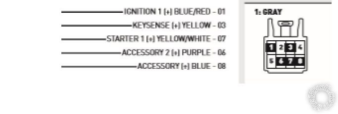
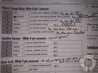
Please note that Pin 3 is Keysense and mandatory. You can power it as IGN2 (+) but will need a relay.
And here is a diagram for the Parking Lights :
Avital Remote Start 4115L, 2006 Volvo XC90 -- posted image.
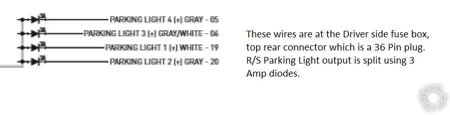
You will need four 3 Amp diodes to split the 4115's lone (+) Parking Light output. Make sure the 4115's
Parking Light jumper is set tp (+).
Soldering is fun!
robxc90 
Member - Posts: 2
Member spacespace
Joined: February 01, 2020
Location: Virginia, United States
Posted: February 03, 2020 at 6:03 PM / IP Logged Link to Post Post Reply Quote robxc90
Thank you so much for posting some advice......clearly I really need it!! Struggled all,weekend and still notHing to show for it.
Hopefully these pics will,come thru explaining what I’ve done so far .....but it ain’t working yet.
I read up on the d2d and it sounds like this makes all connections needed except the power and ground? Am I reading too much into that? As you’ll see I assumed many wires could be left out (for now) and that the thing would work as long as I didn’t lock the car and left the key in ignition or near ignition so it reads the chip and would not need an immobile bypassing device...
This is definitely not easy and I’m usually pretty good with stuff like this, or so I thought....but the directions suck. Terrible help from the manufacturer too...
Avital Remote Start 4115L, 2006 Volvo XC90 -- posted image.
kreg357 
Platinum - Posts: 7,787
Platinum spaceThis member has made a donation to the12volt.com. Click here for more info.spaceThis member has been recognized as an authority in Electrical Theory. Click here for more info.spaceThis member has been recognized as an authority in Mobile Security and Convenience. Click here for more info.spacespace
Joined: January 30, 2009
Location: Pennsylvania, United States
Posted: February 03, 2020 at 6:49 PM / IP Logged Link to Post Post Reply Quote kreg357
Yep, those pic's are a bit hard to read. Just fill in the below list.
Here is a wire chart for the Viper 4115 :
4115
Primary Harness, 9-pin connector
1 LIGHT GREEN BLACK (-) 200mA FACTORY ALARM DISARM OUTPUT
2 GREEN/WHITE (-) 200mA FACTORY ALARM REARM OUTPUT
3 YELLOW (+) IGNITION OUT (TO ALARM)
4 WHITE/BLUE (-) ACTIVATION INPUT
5 ORANGE (-) 500mA GROUND WHEN LOCKED/ANTI-GRIND OUTPUT
6 BROWN (-) 200mA HORN OUTPUT
7 RED/WHITE (-) 200mA TRUNK RELEASE OUTPUT
8 BLACK GROUND INPUT
9 WHITE (+/-) LIGHT FLASH OUTPUT    
Remote Start harness, 5-pin connector
1 BLACK/WHITE (-) NEUTRAL SAFETY SWITCH INPUT
2 VIOLET/WHITE TACHOMETER INPUT              
3 BROWN (+) BRAKE SHUTDOWN INPUT
4 GRAY (-) HOOD PIN SWITCH SHUTDOWN INPUT
5 BLUE/WHITE (-) 200 mA 2ND STATUS/REAR DEFOGGER OUTPUT
Heavy Gauge Relay, 6-pin connector
1 PINK OUTPUT TO PRIMARY IGNITION CIRCUIT
2 PURPLE OUTPUT TO STARTER CIRCUIT
3 ORANGE OUTPUT TO ACCESSORY CIRCUIT
4 RED (+) (30A) HIGH CURRENT 12V INPUT
5 PINK/WHITE OUTPUT TO SECOND IGNITION/ACCESSORY CIRCUIT
6 RED (+) (30A) HIGH CURRENT 12V INPUT
Satellite harness - 4-pin connector
1 BLUE (-) 200mA STATUS OUTPUT          
2 ORANGE (-) 200mA ACCESSORY OUTPUT
3 PURPLE (-) 200mA STARTER OUTPUT
4 PINK (-) 200mA IGNITION OUTPUT
Door Lock, 3-pin connector
1 LIGHT BLUE (-) UNLOCK OUTPUT            
2 EMPTY NOT USED
3 GREEN (-) LOCK OUTPUT
Soldering is fun!

If you wish to post a reply to this topic, you must first login.
If you are not already registered, you must first register.

  Printable version Printable version Post ReplyPost New Topic
You cannot post new topics in this forum
You cannot reply to topics in this forum
You cannot delete your posts in this forum
You cannot edit your posts in this forum
You cannot create polls in this forum
You cannot vote in polls in this forum

  •  
Search the12volt.com
Follow the12volt.com Follow the12volt.com on Facebook
Friday, May 17, 2024 • Copyright © 1999-2024 the12volt.com, All Rights Reserved Privacy Policy & Use of Cookies
Disclaimer: *All information on this site ( the12volt.com ) is provided "as is" without any warranty of any kind, either expressed or implied, including but not limited to fitness for a particular use. Any user assumes the entire risk as to the accuracy and use of this information. Please verify all wire colors and diagrams before applying any information.

Secured by Sectigo
the12volt.com spacer
Support the12volt.com
Top
the12volt.com spacer