the12volt.com spacer
icon

prostart CT3300 door locks


Post ReplyPost New Topic
< Prev Topic Next Topic >
here2for 
Member - Posts: 3
Member spacespace
Joined: October 26, 2005
Location: Canada
Posted: October 27, 2005 at 8:46 PM / IP Logged  
Hi all,
I am installing the above unit on a '04 CHEVY TRACKER. The remote has 4 buttons,lock/unlock start and trunk(n/a)
Prostart says in the instructions to connect the grn wire on the 12 pin acc harness to the pnk/grn and the brn on the 12 pin acc harness to the pink. It says the wires on the vehicle are located to the right of the steering column - which they are. I connected as described and nothing happens. prostart CT3300 door locks -- posted image. 
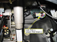
The instructions on prostarts website say that the pink & pink/grn are + but there picture shows them as - ?? In any event if anyone knows how to make it work or can offer advice it would be much appreciated.
Thank You, Chuck
here2for
mo12v 
Platinum - Nominee - Posts: 2,748
Platinum - Nominee spaceThis member consistently provides reliable informationspace
Joined: September 30, 2003
Location: Afghanistan
Posted: October 27, 2005 at 9:01 PM / IP Logged  

Isn't  your ProStart EITHER Positive or Negative Lock Output??

If NOT you will need Relays

http://www.directechs.com/directwire/wire_body.asp?action=select&yr=5661&product=Remote%20Start

MO
Don't Learn from Others Mistakes
You Might Be the One That Knows.
Velocity Motors 
Moderator - Posts: 12,488
Moderator spaceThis member has made a donation to the12volt.com. Click here for more info.spaceThis member has been recognized as an authority in Electrical Theory. Click here for more info.spaceThis member has been recognized as an authority in Fabrication. Click here for more info.spaceThis member has been recognized as an authority in Mobile Audio and Video. Click here for more info.spaceThis member has been recognized as an authority in Mobile Security and Convenience. Click here for more info.spacespace
Joined: March 08, 2002
Location: Manitoba, Canada
Posted: October 27, 2005 at 9:07 PM / IP Logged  
You will need relays for this connection. (-) trigger from ProStart that requires reversal to (+). Use this digram with 2 SPDT relays:
http://www.velocitymotorsport.com/images/install_notes/N2P.jpg
Jeff
Velocity Custom Home Theater
Mobile Audio/Video Specialist
Morden, Manitoba CANADA
here2for 
Member - Posts: 3
Member spacespace
Joined: October 26, 2005
Location: Canada
Posted: October 27, 2005 at 9:09 PM / IP Logged  
Prostart says they are neg....how do I make them work if that is the case ? :)
here2for
mo12v 
Platinum - Nominee - Posts: 2,748
Platinum - Nominee spaceThis member consistently provides reliable informationspace
Joined: September 30, 2003
Location: Afghanistan
Posted: October 27, 2005 at 9:58 PM / IP Logged  

2 SPDT Relays:

Relay 1

LOCK:

PIN 87 = Constant 12 volt ( + )
PIN 87a = XX
PIN 30 = LOCK Wire
PIN 85 = Negative Lock Output from ProStart
PIN 86 = Constant 12 volt ( + )

Relay 2

UNLOCK:

PIN 87 =Constant 12 volt ( + )
PIN 87a = XX
PIN 30 = UNLOCK Wire
PIN 85 = Negative UNLock Output from ProStart
PIN 86 = Constant 12 volt ( + )

MO
Don't Learn from Others Mistakes
You Might Be the One That Knows.
here2for 
Member - Posts: 3
Member spacespace
Joined: October 26, 2005
Location: Canada
Posted: October 29, 2005 at 9:24 PM / IP Logged  
Hey Guys, Thanks to all for your help and advice. problem solved
Regards, Chuck
here2for

Sorry, you can NOT post a reply.
This topic is closed.

  Printable version Printable version Post ReplyPost New Topic
You cannot post new topics in this forum
You cannot reply to topics in this forum
You cannot delete your posts in this forum
You cannot edit your posts in this forum
You cannot create polls in this forum
You cannot vote in polls in this forum

  •  
Search the12volt.com
Follow the12volt.com Follow the12volt.com on Facebook
Thursday, May 16, 2024 • Copyright © 1999-2024 the12volt.com, All Rights Reserved Privacy Policy & Use of Cookies
Disclaimer: *All information on this site ( the12volt.com ) is provided "as is" without any warranty of any kind, either expressed or implied, including but not limited to fitness for a particular use. Any user assumes the entire risk as to the accuracy and use of this information. Please verify all wire colors and diagrams before applying any information.

Secured by Sectigo
the12volt.com spacer
Support the12volt.com
Top
the12volt.com spacer