the12volt.com spacer
icon

90 astro van keyless entry


Post ReplyPost New Topic
< Prev Topic Next Topic >
thegoose 
Member - Posts: 20
Member spacespace
Joined: January 05, 2006
Location: United States
Posted: January 07, 2006 at 3:42 PM / IP Logged  

im installing a (aftermarket generation aga0801) keyless entry on my 90 astro van. it will unlock but wont lock. when i hit the unlock button on the remote it lites up my test light, but wont light up my test lite on when i hit the remote lock button. i am hooked to the light blue (lock) and the BLACK/ white (unlock) im not using the engine cut off at all. i cant figuar out if im making a mistake or if the entry system is broke? here is 2 bad photos of the wire diagrams.

any help would be great!

thanks thegoose

90 astro van keyless entry -- posted image.

90 astro van keyless entry -- posted image.

the goose
mo12v 
Platinum - Nominee - Posts: 2,748
Platinum - Nominee spaceThis member consistently provides reliable informationspace
Joined: September 30, 2003
Location: Afghanistan
Posted: January 07, 2006 at 4:36 PM / IP Logged  
Did you hook up 2 wires from AGA0801 to Constant 12 Volts or just 1?
Also, did you verify Both the LOCK & Unlock wires with the Door Switch?
MO
Don't Learn from Others Mistakes
You Might Be the One That Knows.
thegoose 
Member - Posts: 20
Member spacespace
Joined: January 05, 2006
Location: United States
Posted: January 07, 2006 at 4:51 PM / IP Logged  

mo12v wrote:
Did you hook up 2 wires from AGA0801 to Constant 12 Volts or just 1?
Also, did you verify Both the LOCK & Unlock wires with the Door Switch?

i hooked the red and both yellow wires to the positive like in the diagram, i thought it was weird to hook both yellows to the positive but thats what it says to do.  and i did check the wires with a test light to see that i had the right wires.       im wondering if not hooking up the white - acc, blue/black - trunk, yellow - engine cut off, pink - siren, might have something to do with it?????????????

the goose
mo12v 
Platinum - Nominee - Posts: 2,748
Platinum - Nominee spaceThis member consistently provides reliable informationspace
Joined: September 30, 2003
Location: Afghanistan
Posted: January 07, 2006 at 4:56 PM / IP Logged  

thegoose wrote:
i hooked the red and both yellow wires to the positive like in the diagram, i

Doesn't the YELLOW / Black have to go to Constant 12 Volt + also?

I can't see the Diagrams very clear.........

MO
Don't Learn from Others Mistakes
You Might Be the One That Knows.
thegoose 
Member - Posts: 20
Member spacespace
Joined: January 05, 2006
Location: United States
Posted: January 07, 2006 at 5:02 PM / IP Logged  
mo12v wrote:

thegoose wrote:
i hooked the red and both yellow wires to the positive like in the diagram, i

Doesn't the YELLOW / Black have to go to Constant 12 Volt + also?

I can't see the Diagrams very clear.........

sorry thats what i ment the red and the yellow and the yellow/black all to the positive 12v

the goose
mo12v 
Platinum - Nominee - Posts: 2,748
Platinum - Nominee spaceThis member consistently provides reliable informationspace
Joined: September 30, 2003
Location: Afghanistan
Posted: January 07, 2006 at 5:09 PM / IP Logged  
If so, and you do NOT get a 12 Volt reading when you Press LOCK on Remote........( Keys are NOT in Ignition )..........I would want to make sure of wiring, Fuse/s, Programming and then Replace Unit..........
MO
Don't Learn from Others Mistakes
You Might Be the One That Knows.
thegoose 
Member - Posts: 20
Member spacespace
Joined: January 05, 2006
Location: United States
Posted: January 07, 2006 at 5:18 PM / IP Logged  

mo12v wrote:
If so, and you do NOT get a 12 Volt reading when you Press LOCK on Remote........( Keys are NOT in Ignition )..........I would want to make sure of wiring, Fuse/s, Programming and then Replace Unit..........

its possibly it is a programing problem the instructions are a bit confusing to me. im going to try to program it again if it dont work im going to assume it is defective. unless this has happen to any one else.    

thanks for your help

thegoose

the goose
mo12v 
Platinum - Nominee - Posts: 2,748
Platinum - Nominee spaceThis member consistently provides reliable informationspace
Joined: September 30, 2003
Location: Afghanistan
Posted: January 07, 2006 at 5:22 PM / IP Logged  
Have you checked to see if you get Output from any other wires on the AGA0801 Lock / Unlock wires, when you Press LOCK on the Remote?
MO
Don't Learn from Others Mistakes
You Might Be the One That Knows.
thegoose 
Member - Posts: 20
Member spacespace
Joined: January 05, 2006
Location: United States
Posted: January 07, 2006 at 5:27 PM / IP Logged  

mo12v wrote:
Have you checked to see if you get Output from any other wires on the AGA0801 Lock / Unlock wires, when you Press LOCK on the Remote?

i did check the other wires (excpt the yellow/black and yellow that are hooked to the positive 12v) none light up.

the goose
dualsport 
Silver - Posts: 983
Silver spacespace
Joined: September 27, 2005
Location: United States
Posted: January 07, 2006 at 11:29 PM / IP Logged  
90 astro van keyless entry -- posted image.
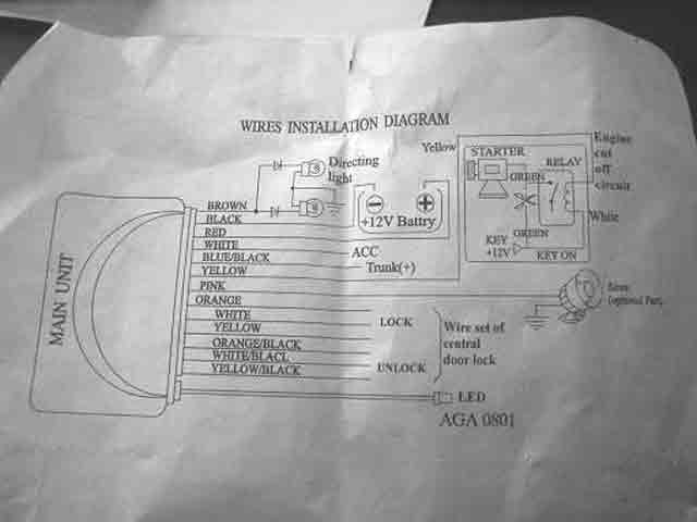
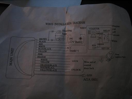
You didn't hook up the yellow wire from the top of the "WIRES INSTALLATION DIAGRAM" to 12V, did you? That's a relay control signal for the starter cutout; connecting it to 12V will blow it-
It looks like the WHITE wire is for LOCK, where does the light blue show up?
Page of 2

  Printable version Printable version Post ReplyPost New Topic
You cannot post new topics in this forum
You cannot reply to topics in this forum
You cannot delete your posts in this forum
You cannot edit your posts in this forum
You cannot create polls in this forum
You cannot vote in polls in this forum

  •  
Search the12volt.com
Follow the12volt.com Follow the12volt.com on Facebook
Saturday, May 4, 2024 • Copyright © 1999-2024 the12volt.com, All Rights Reserved Privacy Policy & Use of Cookies
Disclaimer: *All information on this site ( the12volt.com ) is provided "as is" without any warranty of any kind, either expressed or implied, including but not limited to fitness for a particular use. Any user assumes the entire risk as to the accuracy and use of this information. Please verify all wire colors and diagrams before applying any information.

Secured by Sectigo
the12volt.com spacer
Support the12volt.com
Top
the12volt.com spacer