the12volt.com spacer
icon

2003 maxima, ultrastart 1270tl


Post ReplyPost New Topic
< Prev Topic Next Topic >
peterubers 
Silver - Posts: 706
Silver spaceThis member has made a donation to the12volt.com. Click here for more info.spacespace
Joined: December 29, 2006
Location: United States
Posted: March 13, 2007 at 10:58 PM / IP Logged  

I need to use my GWR(-) to trigger several things in an '03 Maxima --

1) Bypasskit immobilizer bypass

2) Antigrind relay

How do I diode isolate it?  Thanks

The search function is your friend.
peterubers 
Silver - Posts: 706
Silver spaceThis member has made a donation to the12volt.com. Click here for more info.spacespace
Joined: December 29, 2006
Location: United States
Posted: March 13, 2007 at 11:00 PM / IP Logged  

... it's a GREEN / WHITE wire in the SECOND wire harness behind the HVAC cluster

It has a 12.4-ish voltage that needs a pulsed or latched negative(-).

The search function is your friend.
KarTuneMan 
Platinum - Posts: 7,056
Platinum spaceThis member has made a donation to the12volt.com. Click here for more info.spaceThis member consistently provides reliable informationspace
Joined: December 14, 2004
Location: Isle Of Man
Posted: March 13, 2007 at 11:18 PM / IP Logged  
Theres a FAT green wire in the drivers kick. POS(+) trigger....latched!
KarTuneMan 
Platinum - Posts: 7,056
Platinum spaceThis member has made a donation to the12volt.com. Click here for more info.spaceThis member consistently provides reliable informationspace
Joined: December 14, 2004
Location: Isle Of Man
Posted: March 13, 2007 at 11:24 PM / IP Logged  

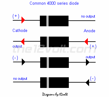
2003 maxima, ultrastart 1270tl -- posted image.You want to be able to "put thru" ground, and NOT have any voltage "feed back."

Install your diodes on SEPERATE wires for each to be triggered with the cathod towards the device to be triggered.

the12volt 
Administrator - Posts: 3,955
Administrator spaceThis member has made a donation to the12volt.com. Click here for more info.spaceThis member has been recognized as an authority in Electrical Theory. Click here for more info.spaceThis member has been recognized as an authority in Mobile Audio and Video. Click here for more info.spaceThis member has been recognized as an authority in Mobile Security and Convenience. Click here for more info.spacespace
Joined: March 07, 2002
Location: Louisiana, United States
Posted: March 14, 2007 at 8:09 AM / IP Logged  
KarTuneMan wrote:
...Install your diodes on SEPERATE wires for each to be triggered with the cathod towards the device to be triggered.
You want the ANODE side of each diode toward the device you want to receive ground from your ground while running wire. The cathode side (side with stripe) of each diode should be connected to the ground while running wire. 
2003 maxima, ultrastart 1270tl -- posted image. the12volt • Support the12volt.com
KarTuneMan 
Platinum - Posts: 7,056
Platinum spaceThis member has made a donation to the12volt.com. Click here for more info.spaceThis member consistently provides reliable informationspace
Joined: December 14, 2004
Location: Isle Of Man
Posted: March 14, 2007 at 8:13 AM / IP Logged  
It appears Im dyslexic....and wetahded.....looking right at the 3rd diagram....2003 maxima, ultrastart 1270tl -- posted image.
peterubers 
Silver - Posts: 706
Silver spaceThis member has made a donation to the12volt.com. Click here for more info.spacespace
Joined: December 29, 2006
Location: United States
Posted: March 14, 2007 at 11:29 AM / IP Logged  
Hmm... good stuff... so I can use GWR(-) to relay 12volts(fused) from the engine to the this fat green wire?
The search function is your friend.
peterubers 
Silver - Posts: 706
Silver spaceThis member has made a donation to the12volt.com. Click here for more info.spacespace
Joined: December 29, 2006
Location: United States
Posted: March 16, 2007 at 1:08 PM / IP Logged  

Installed an Ultrastart 1270TL in an '03 Nissan Maxima -- everything works flawlessly -- one catch:

When you remote start and then remote shutdown without ever getting into the car to turn the key to "III" and hit the brake and start driving -- the auto headlights never shut off -- they remain on (presumably until the battery dies -- although I didn't wait that long).

Is there a quick way to wire something such that the auto headlights will go off when I remote shut down?  Thanks

The search function is your friend.
Bnluis 
Silver - Posts: 578
Silver spacespace
Joined: December 24, 2002
Location: New York, United States
Posted: March 16, 2007 at 1:16 PM / IP Logged  
Yes look for the wire in your alarm / starter that gives a negative pulse when remote starter shuths down and connect it to the drivers door tigger wire at the BCM. I belive is light blue. This way when the remote starter shuts down  it will trigger the the door thus making look like you opened the door and close it, then after about 30 to 35 second the auto light will shut down.  Keep us posted.
Luis
Sound Waves
Is up to the installer to test all wires with a DMM whenever possible.
peterubers 
Silver - Posts: 706
Silver spaceThis member has made a donation to the12volt.com. Click here for more info.spacespace
Joined: December 29, 2006
Location: United States
Posted: March 16, 2007 at 2:30 PM / IP Logged  

I'm not sure if the Ultrastart has a wire that pulses negative after remote shutdown --

I guess i could relay the signal from the horn wire (off the Ultrastart 1270TL) to the BCM and give that BCM door trigger wire a negative pulse (the ultrastart will honk twice after remote shutdown).

thanks for the tip, will let you know how it goes

The search function is your friend.
Page of 3

  Printable version Printable version Post ReplyPost New Topic
You cannot post new topics in this forum
You cannot reply to topics in this forum
You cannot delete your posts in this forum
You cannot edit your posts in this forum
You cannot create polls in this forum
You cannot vote in polls in this forum

  •  
Search the12volt.com
Follow the12volt.com Follow the12volt.com on Facebook
Sunday, May 19, 2024 • Copyright © 1999-2024 the12volt.com, All Rights Reserved Privacy Policy & Use of Cookies
Disclaimer: *All information on this site ( the12volt.com ) is provided "as is" without any warranty of any kind, either expressed or implied, including but not limited to fitness for a particular use. Any user assumes the entire risk as to the accuracy and use of this information. Please verify all wire colors and diagrams before applying any information.

Secured by Sectigo
the12volt.com spacer
Support the12volt.com
Top
the12volt.com spacer