


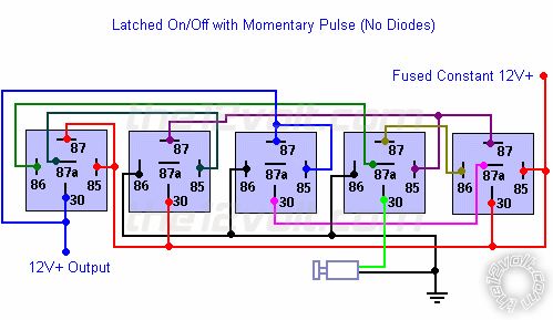
momentary to latched output


Posted: September 21, 2010 at 7:54 AM / IP Logged


Posted: September 21, 2010 at 8:36 AM / IP Logged
Posted: September 21, 2010 at 8:56 AM / IP Logged
Posted: September 21, 2010 at 9:37 AM / IP Logged

Posted: September 21, 2010 at 10:20 AM / IP Logged
Posted: September 21, 2010 at 10:30 AM / IP Logged


Posted: September 21, 2010 at 12:10 PM / IP Logged
Posted: September 21, 2010 at 4:43 PM / IP Logged
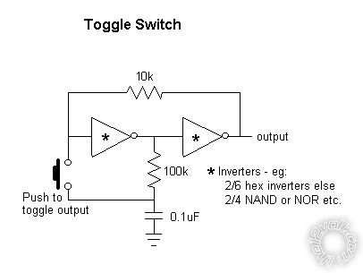 It's only 2 inverters - hence you could have 3 toggle switches per HEX inverter package, or 2 per quad NAND or NOR package (connect their inputs together to act as inverters). (A package being a 14-pin IC.)
I think it powers up in the OFF state.
An output buffer (transistor/FET) is probably required (but depending on what device is chosen and what load).
I'm sure transistors or FETs can be used instead of integrated inverters....
It's only 2 inverters - hence you could have 3 toggle switches per HEX inverter package, or 2 per quad NAND or NOR package (connect their inputs together to act as inverters). (A package being a 14-pin IC.)
I think it powers up in the OFF state.
An output buffer (transistor/FET) is probably required (but depending on what device is chosen and what load).
I'm sure transistors or FETs can be used instead of integrated inverters....Posted: September 22, 2010 at 8:24 AM / IP Logged
Posted: September 24, 2010 at 8:43 AM / IP Logged
Sorry, you can NOT post a reply.
This topic is closed.
 Printable version
| You cannot post new topics in this forum You cannot reply to topics in this forum You cannot delete your posts in this forum You cannot edit your posts in this forum You cannot create polls in this forum You cannot vote in polls in this forum |

| Search the12volt.com |
Follow the12volt.com 
Friday, July 18, 2025 • Copyright © 1999-2025 the12volt.com, All Rights Reserved • Privacy Policy & Use of Cookies

Friday, July 18, 2025 • Copyright © 1999-2025 the12volt.com, All Rights Reserved • Privacy Policy & Use of Cookies
Disclaimer:
*All information on this site ( the12volt.com ) is provided "as is" without any warranty of any kind, either expressed or implied, including but not limited to fitness for a particular use. Any user assumes the entire risk as to the accuracy and use of this information. Please
verify all wire colors and diagrams before applying any information.
