the12volt.com spacer
icon

+12 constant to momentary


Post ReplyPost New Topic
< Prev Topic Next Topic >
guyfromhe 
Member - Posts: 8
Member spacespace
Joined: December 10, 2010
Posted: December 10, 2010 at 6:58 PM / IP Logged  
First off I am trying to reset a device when the car is started by pulsing it's power line for half a second or so.. (I have a +12v line that's active when the car is running) I have a 12V relay, a 1000 uf Cap and some resistors. I am testing with a bench supply right now so I don't know if that's part of my problem, but I will try it on my battery later tonight.
I have the + power for my device connected to the NC lines on the relay so when it's actuated the power is off otherwise it's powered up.
I have the - side of the 12v supply connected to the end of the cap which is in turn connected to the trigger lines on the relay. the other end has +12v on it. The first time I connect the +12v it toggles and works perfectly but then after that it doesn't work again until I manually short out the cap to discharge it.
I tried putting a resistor and a light across the cap to discharge it but when that is in place the relay latches and does not give momentary pulses anymore.
I am at a loss at this point and hoping someone can tell me what I am doing wrong.
Thanks in advance guys.
oldspark 
Gold - Posts: 4,913
Gold spacespace
Joined: November 03, 2008
Location: Australia
Posted: December 10, 2010 at 7:21 PM / IP Logged  
guyfromhe 
Member - Posts: 8
Member spacespace
Joined: December 10, 2010
Posted: December 10, 2010 at 8:36 PM / IP Logged  
Yes.
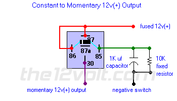
That's the circuit I tried to create.
Without the resistor I have to drain the cap manually and with the resistor the relay latches.
guyfromhe 
Member - Posts: 8
Member spacespace
Joined: December 10, 2010
Posted: December 10, 2010 at 8:46 PM / IP Logged  
Just tried it in my car with the battery and it has the exact same results.
Latches with resistor and only toggles until the cap charges then it won't toggle anymore until it's discharged manually.
i am an idiot 
Platinum - Posts: 13,671
Platinum spaceThis member consistently provides reliable informationspace
Joined: September 21, 2006
Location: Louisiana, United States
Posted: December 10, 2010 at 8:50 PM / IP Logged  
I know that circuit works flawlessly.  Did you put the Diode across 85 and 86?. 
guyfromhe 
Member - Posts: 8
Member spacespace
Joined: December 10, 2010
Posted: December 10, 2010 at 9:07 PM / IP Logged  
Yes I did, I tried with and without.
Maybe I am wiring it wrong somehow?
The relay has 2 pins for the coils
One pin has the positive side of the cap on it then attached between the legs of the cap is the resistor on the negative end of the cap I have the (-) terminal.
The other coil lead has just the (+) lead on it.
There is a diode running from one pin to the other.
I am new at this, is this wired the way it should be or did I do something wrong?
Thanks.
oldspark 
Gold - Posts: 4,913
Gold spacespace
Joined: November 03, 2008
Location: Australia
Posted: December 10, 2010 at 9:26 PM / IP Logged  
The resistor value is too low (else the coil too high).
It is in series with the coil, hence a resistor divider.
But 10k should be fine.
Maybe if you are using 1k or less.
IE - if it's a 250R (Ohm) coil, then 250T-1000R = 1R:4R is a 1:5 divider (from 250/(250+1k) or 1/(1+4) = 1/5).
So at say 12V, 12/5 = 2.4V across the coil. Probably not enough to pull it in (ie, switch on or energise the relay), but likely to hold in - ie, it won't let go.
Increasing the resistor value merely increases the time the relay stays on - ie, it takes the cap longer to drain (through a larger resistor).
The diode isn't necessary though its inclusion means instant cap discharge if the "fused +12V" is grounded when NOT present. EG - an IGN switch is +12V when on, but MAY be effectively grounded when off because of other things it powers (ie, any loads IGN powers are grounded; even if only relays or meters etc, they can form a reasonable ground path.)
FYI - I now question how many circuits I have stated that the diode is "only" for spike suppression when it may have some other function. (What was it the other day....?)
Hence I rarely include spike suppression diodes - IMO they should be a "general caveat" for any relay, though I might add a "don't forget..." or "suppression not included", else include it with "for suppression only". I can't recall where anyone has stated "diode is required for operation...".
guyfromhe 
Member - Posts: 8
Member spacespace
Joined: December 10, 2010
Posted: December 10, 2010 at 9:48 PM / IP Logged  
Thanks.
I don't care so much about how long it stays on or off so much but I need it to toggle every time it gets power.
I don't have a lot of resistors here and I don't know if I have a 10k or not.. I will poke them with the multimeter and see what I get.
If the resistance is too low it will stay on? I will get some higher value resistors and try again if you think that will make a difference.
Here is the relay specs:
12VDC 4PDT relay
75MA 160 ohm coil
5A@28vdc or 250 vac
Thanks.
guyfromhe 
Member - Posts: 8
Member spacespace
Joined: December 10, 2010
Posted: December 10, 2010 at 11:02 PM / IP Logged  
I got a 10 k trim pot because all my resistors were like 50 ohms and it worked. Guess following directions helps :P
Thanks for the support.

Sorry, you can NOT post a reply.
This topic is closed.

  Printable version Printable version Post ReplyPost New Topic
You cannot post new topics in this forum
You cannot reply to topics in this forum
You cannot delete your posts in this forum
You cannot edit your posts in this forum
You cannot create polls in this forum
You cannot vote in polls in this forum

  •  
Search the12volt.com
Follow the12volt.com Follow the12volt.com on Facebook
Saturday, May 11, 2024 • Copyright © 1999-2024 the12volt.com, All Rights Reserved Privacy Policy & Use of Cookies
Disclaimer: *All information on this site ( the12volt.com ) is provided "as is" without any warranty of any kind, either expressed or implied, including but not limited to fitness for a particular use. Any user assumes the entire risk as to the accuracy and use of this information. Please verify all wire colors and diagrams before applying any information.

Secured by Sectigo
the12volt.com spacer
Support the12volt.com
Top
the12volt.com spacer