the12volt.com spacer
icon

puzzled, dpdt relay and sensing


Post ReplyPost New Topic
< Prev Topic Next Topic >
midlifez 
Member - Posts: 6
Member spacespace
Joined: March 14, 2012
Posted: March 14, 2012 at 1:44 PM / IP Logged  

Stumped...

Bought some JDM electric folding mirrors for my car. What I wanted, and have accomplished, is for them to automatically fold closed when the car is turned off and automatically fold out when the car is turned on again. So far so good.

I accomplished this by way of a DPDT relay. The mirrors work such that when + and - are connected to the motor one direction they fold in, reverse polarity and the fold out.

What I am wanting do now though is hook up the physicaly switch whic allows manual control of the folding in/out action of the mirrors. What I need is a way to have so that after the car is turned on and the mirror has been unfolded power is cut to it afer 20 seconds. The reason is there is no way to know what position the manual folding mirror switch is in and thus if it had been left in the closed/folding position and the DPDT relay then attempted to unfold the mirror upon turing the car on it would short out.  I also thought about putting a DEI 528t spliced in between the ACC source (the yellow wire below) and the DPDT relay where the 528t would then supply power for 20 seconds, the relay would then unfold the mirrors and using another 528t to cut power to the manual mirror switch assembly for 30 seconds. Problem in this scenario is when power is not present at the ACC + line, as would be the case after the expiration of the 20 seconds via the 528t, the DPDT would then fold the mirrors back in..

Some starting points:

1. The manual switch is the one which came with the mirrors and is THE switch which I want to use as it matches the interior, etc.

2. The manual switch is part of other switches (control of mirror angle, etc.) and only receives power when the car is turned on.
3. The manual mirror folding switch has only two functions: A. fold mirrors in or B . reverse polarity of + and - to them which folds the mirrors out

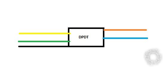
Below is a paint pic I made to show the current function of the DPDT relay:

- Yellow is "accessory" power, i.e. + which is only supplied when the car is on
- Green is constant + power, i.e. always on
- Black is ground
- Brown and Blue are connected to the folding mirror motor and are either + or - depending on which way the mirror is to be folded.

puzzled, dpdt relay and sensing -- posted image.

I have the part solved for the power at the manual switch itself; going to use a DEI 528t which will be spliced into the ACC power wire to the switch assemble. When it detects power it will not allow power to pass through until 30 seconds have elapsed.

Any ideas from some electronic gurus? My first post here and yes, have searched...

KPierson 
Platinum - Posts: 3,527
Platinum spaceThis member consistently provides reliable informationspace
Joined: April 14, 2005
Location: Ohio, United States
Posted: March 14, 2012 at 4:31 PM / IP Logged  
How about tying it in to door lock/unlock pulses. You could set it up so that if the ignition is not on and a door lock pulse is received it latches a timed relay on for X seconds. The same for unlock.
Kevin Pierson
midlifez 
Member - Posts: 6
Member spacespace
Joined: March 14, 2012
Posted: March 14, 2012 at 5:09 PM / IP Logged  

KPierson wrote:
How about tying it in to door lock/unlock pulses. You could set it up so that if the ignition is not on and a door lock pulse is received it latches a timed relay on for X seconds. The same for unlock.

After much noodling think I MAY have found a solution:

A. Put a 528t on the output wires, i.e. NOT supply side, of the existing DPDT relay, with the 528t set to detect change in polarity from + to - or - to + with them timed to pass through for 15 seconds.

B. Then on the + and - feeding into the mirror control switch assembly so the two 528t's cut power to them for 20 seconds.

In this fashion when the car is turned on the (A) 528t's on the output side of the DTDP will supply power and unfold the mirrors and then after 15 seconds cut power while the (B) 528t's will not allow power for 20 seconds so as to avert possibility of shorting due to the position of the manual folding mirror switch.

Thoughts?

wiring in to door locks is problematic for other reasons.

howie ll 
Pot Metal - Posts: 16,466
Pot Metal spacespace
Joined: January 09, 2007
Location: United Kingdom
Posted: March 15, 2012 at 4:37 AM / IP Logged  
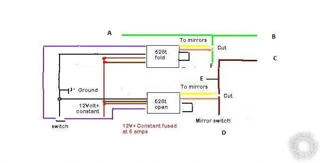
Use this diagram, note the violet wire represents the 528t BLACK/ white trigger wire. I've used as switch to ground both but it you followed the rules and told us what car, as Kevin says, I'm sure we could resolve this via lock or ignition.
howie ll 
Pot Metal - Posts: 16,466
Pot Metal spacespace
Joined: January 09, 2007
Location: United Kingdom
Posted: March 15, 2012 at 4:39 AM / IP Logged  
Think I should have posted it! 55B_mirror_fold.bmp
howie ll 
Pot Metal - Posts: 16,466
Pot Metal spacespace
Joined: January 09, 2007
Location: United Kingdom
Posted: March 15, 2012 at 4:40 AM / IP Logged  
Do you know I think my diagram is WRONG,, I think I can use one each for open and fold!
howie ll 
Pot Metal - Posts: 16,466
Pot Metal spacespace
Joined: January 09, 2007
Location: United Kingdom
Posted: March 15, 2012 at 5:00 AM / IP Logged  
Sorry, I did the original some time ago, newer version!
79C_mirror_fold.bmp
On fold run it to an ignition wire and diode with a 1N4004, band towards the ignition.
On the 528t used to OPEN the mirrors, from the ignition side of your first join, run a wire to the open 528t BLACK/ white, this time cut the loop on that 528t and diode 1N4004 the other way round, i.e. band away from ignition.
This will give you close on turning off ignition, open on turning on ignition. Set the 528t internal timers for 1 second longer than it takes to open or fold the mirrors.
midlifez 
Member - Posts: 6
Member spacespace
Joined: March 14, 2012
Posted: March 15, 2012 at 6:55 AM / IP Logged  

It is a 1990 Nissan 300ZX Twin Turbo

This model year does not have a remote controlled lock/unlock. The driver side door keylock does lock/unlock when turned though... Interested in solution using that.

THANKS!

midlifez 
Member - Posts: 6
Member spacespace
Joined: March 14, 2012
Posted: March 15, 2012 at 7:34 AM / IP Logged  

howie ll wrote:
Sorry, I did the original some time ago, newer version!
79C_mirror_fold.bmp
On fold run it to an ignition wire and diode with a 1N4004, band towards the ignition.
On the 528t used to OPEN the mirrors, from the ignition side of your first join, run a wire to the open 528t BLACK/ white, this time cut the loop on that 528t and diode 1N4004 the other way round, i.e. band away from ignition.
This will give you close on turning off ignition, open on turning on ignition. Set the 528t internal timers for 1 second longer than it takes to open or fold the mirrors.

OK, just so I am clear, looking at the last image you posted the connections are as in the image I posted, I enlarged it and labled each connection. Am also confused as I dont see any switch/accessory power connection, i.e. one which is only hot when the car is turned on.

A: Mirror

B: Mirror
C:?
D:Manual mirror switch
E: ?
F: ?

puzzled, dpdt relay and sensing -- posted image.

howie ll 
Pot Metal - Posts: 16,466
Pot Metal spacespace
Joined: January 09, 2007
Location: United Kingdom
Posted: March 15, 2012 at 10:25 AM / IP Logged  
A + E = driver's door mirror
B + C = passenger's door mirror
D + F = switch
Page of 2

  Printable version Printable version Post ReplyPost New Topic
You cannot post new topics in this forum
You cannot reply to topics in this forum
You cannot delete your posts in this forum
You cannot edit your posts in this forum
You cannot create polls in this forum
You cannot vote in polls in this forum

  •  
Search the12volt.com
Follow the12volt.com Follow the12volt.com on Facebook
Tuesday, May 14, 2024 • Copyright © 1999-2024 the12volt.com, All Rights Reserved Privacy Policy & Use of Cookies
Disclaimer: *All information on this site ( the12volt.com ) is provided "as is" without any warranty of any kind, either expressed or implied, including but not limited to fitness for a particular use. Any user assumes the entire risk as to the accuracy and use of this information. Please verify all wire colors and diagrams before applying any information.

Secured by Sectigo
the12volt.com spacer
Support the12volt.com
Top
the12volt.com spacer