the12volt.com spacer
icon

wiring diagram, switch cameras


Post ReplyPost New Topic
< Prev Topic Next Topic >
buick mackane 
Member - Posts: 4
Member spacespace
Joined: October 10, 2012
Location: Alaska, United States
Posted: October 10, 2012 at 12:09 PM / IP Logged  
Hi all!
Im trying to wire up 3 cameras to my truck.
Right now I have my back up camera coming into my deck and I want to add 2 more cams, a right and left rearview.
I would like to use a 3 position, dpdt switch where the center position would be the rear cam then clicking it to the left would switch to the left cam and to the right to the right cam.
I been playing with some relays and I cant figure out how to switch them.
Also, would it be better to switch the power of the cams or the signal?
Thanks
shortcircuit161 
Silver - Posts: 556
Silver spaceThis member has made a donation to the12volt.com. Click here for more info.spacespace
Joined: August 29, 2010
Location: United States
Posted: October 10, 2012 at 12:58 PM / IP Logged  
I would switch the signal instead of the power wires. That way the cameras are always ready.
I'm sure there are a few ways to wire this, but here goes. The 1st relay controls 2 cameras and the 3rd relay is for camera 3.
This setup would only use the center wire of the video feed and the shields would all go to ground.
You would need a 3 position switch but only connect 2 poles. The switch would provide ground connections to activate each camera.
Relay 1 would be wired as follows:
Pin 85 - 12v constant
Pin 86 - left side contact on switch
Pin 87- video feed from Left Camera
Pin 87a - video feed from Center Camera
Pin 30 - to Pin 87a of Relay 2
Relay 2 would be wired as follows:
Pin 85 - 12v constant
Pin 86 - right side contact on switch
Pin 87 - video output to Headunit/Monitor input
Pin 87a - to Pin 30 of Relay 1
Pin 30 - video feed for Right Camera
The center position on the switch will have No Connections.
Hope that makes sense. I wish I could post the picture I drew to clear up any confusion.
buick mackane 
Member - Posts: 4
Member spacespace
Joined: October 10, 2012
Location: Alaska, United States
Posted: October 10, 2012 at 3:50 PM / IP Logged  
wiring diagram, switch cameras -- posted image.
Thanks Short!
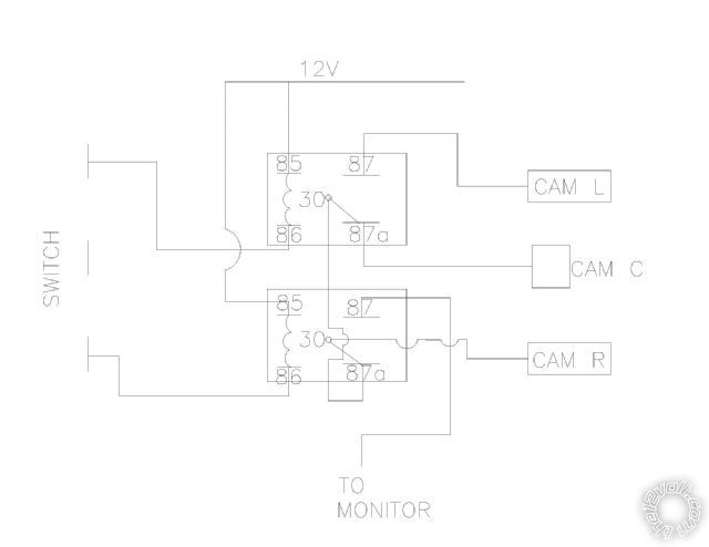
I sketched out the wiring that you described and Im not clear how its going to work.
If the output to the monitor is going to be on 87 (NO) on the second relay, how is the signal gonna get there from the center cam when the switch is on the center position?
Thanks again for your help.
shortcircuit161 
Silver - Posts: 556
Silver spaceThis member has made a donation to the12volt.com. Click here for more info.spacespace
Joined: August 29, 2010
Location: United States
Posted: October 10, 2012 at 4:24 PM / IP Logged  
Oh my goodness! I apologize. I was typing so fast and accidentally inverted Pins 30 and 87 for relay 2.
So it would be Relay 2 as follows:
Relay 2 would be wired as follows:
Pin 85 - 12v constant
Pin 86 - right side contact on switch
Pin 30 - video output to Headunit/Monitor input
Pin 87a - to Pin 30 of Relay 1
Pin 87 - video feed for Right Camera
I also checked the setup for Relay 1 and those pins seem correct.
buick mackane 
Member - Posts: 4
Member spacespace
Joined: October 10, 2012
Location: Alaska, United States
Posted: October 10, 2012 at 5:00 PM / IP Logged  
Thanks Frank. That makes more sense.
BUT! as you flip the switch to the right cam, which will energize relay 2, the center cam will still be on. Will the signal from the center cam be overridden by the right cam?
Thanks.
shortcircuit161 
Silver - Posts: 556
Silver spaceThis member has made a donation to the12volt.com. Click here for more info.spacespace
Joined: August 29, 2010
Location: United States
Posted: October 10, 2012 at 5:43 PM / IP Logged  
You are correct in that as you switch from Left to Right Cameras, you will engage the center camera momentarily.
Once the switch is on the right side, it energizes Relay 2 which opens the connections between Pin 30(common) and Pin 87a (from Relay 1) and connects Pin 30 then to only Pin 87 (right camera).
All cameras are technically always on when your vehicle ignition is on since their 12v and ground are always connected.
Relay 1 at rest (switch at center) turns on Camera Center.
Relay 2 at rest allows the common feed from the monitor (Pin 30) to receive signal from Relay 1 (via Pin 87a).
Relay 1 energized (switch at left) turns on Camera Left.
Relay 2 energized (switch at right) goes direct to Camera Right and no longer connects to Relay 1 at that point.
buick mackane 
Member - Posts: 4
Member spacespace
Joined: October 10, 2012
Location: Alaska, United States
Posted: October 10, 2012 at 6:42 PM / IP Logged  
Brilliant!
Thank you very much Frank.
I'll give it a shot!

Sorry, you can NOT post a reply.
This topic is closed.

  Printable version Printable version Post ReplyPost New Topic
You cannot post new topics in this forum
You cannot reply to topics in this forum
You cannot delete your posts in this forum
You cannot edit your posts in this forum
You cannot create polls in this forum
You cannot vote in polls in this forum

  •  
Search the12volt.com
Follow the12volt.com Follow the12volt.com on Facebook
Thursday, May 9, 2024 • Copyright © 1999-2024 the12volt.com, All Rights Reserved Privacy Policy & Use of Cookies
Disclaimer: *All information on this site ( the12volt.com ) is provided "as is" without any warranty of any kind, either expressed or implied, including but not limited to fitness for a particular use. Any user assumes the entire risk as to the accuracy and use of this information. Please verify all wire colors and diagrams before applying any information.

Secured by Sectigo
the12volt.com spacer
Support the12volt.com
Top
the12volt.com spacer