the12volt.com spacer
icon

4 Channel remote control


Post ReplyPost New Topic
< Prev Topic Next Topic >
mille 
Member - Posts: 8
Member spacespace
Joined: January 04, 2007
Location: United States
Posted: January 04, 2007 at 2:06 AM / IP Logged  
Hello I am trying to wire some linear actuators up to these remote controllers. Ebay has a similar item it is 190023368303.Tried to link the auction sorry.  Each channel has 3 terminals to hook wires up to . There a, b, c, ones nc ,no, c. Ive tried to figure it out but im not getting it. My actuators have 2 wires coming out. Do I need to jump wires to different terminals or what? If someone could please draw me a diagram i would appreciate it very much. thanks
hotwaterwizard 
Silver - Posts: 1,350
Silver spacespace
Joined: December 11, 2003
Location: California, United States
Posted: January 04, 2007 at 8:02 AM / IP Logged  

Here is the Link

http:///.com/dll?ViewItem&item=190023368303&ru=http%3A%2F%2Fsearch.ebay.com%3A80%2Fsearch%2Fsearch.dll%3Ffrom%3DR40%26satitle%3D190023368303%26fvi%3D1

The actuators need just a ground and a hot to actuate.

It can be hooked to the remote but I suggest an external relay if you want all of them actuated at the same time.

A wiring Diagram of the Remote will help. The wiring depends on what you need the actuators to do.

John DeRosa (Hotwaterwizard)
Stockton California
When in doubt, try it out !
mille 
Member - Posts: 8
Member spacespace
Joined: January 04, 2007
Location: United States
Posted: January 04, 2007 at 10:43 AM / IP Logged  
These are 18" linear actuators. They have 2 wires by reversing the wires it changes the direction. In and out. I dont want them to do anything fancy just push one button on remote they move out. push the other they retract.
hotwaterwizard 
Silver - Posts: 1,350
Silver spacespace
Joined: December 11, 2003
Location: California, United States
Posted: January 04, 2007 at 10:56 PM / IP Logged  

What stops the motion?

You may need microswitches in the mix.

John DeRosa (Hotwaterwizard)
Stockton California
When in doubt, try it out !
hotwaterwizard 
Silver - Posts: 1,350
Silver spacespace
Joined: December 11, 2003
Location: California, United States
mille 
Member - Posts: 8
Member spacespace
Joined: January 04, 2007
Location: United States
Posted: January 05, 2007 at 12:05 AM / IP Logged  
Yep thats them. The actuator has micro limit switchs built into it already. I bought the actuator from firgelli automations its the sleek actuator. I also have one of there 4 channel remote systems. It works great. Theres 2 sets of 2 wires coming out,so you can hook 2 actuators up. My project is only using one actuator. Im trying to keep cost down by designing it with the cheaper control. Theres 4 channels on the controller 1channel to extend, one channel to retract. I have looked at every robot build, alarm site trying to see how to wire these. Im stuck now cant figure the wiring out. Thanks again
hotwaterwizard 
Silver - Posts: 1,350
Silver spacespace
Joined: December 11, 2003
Location: California, United States
Posted: January 05, 2007 at 8:10 AM / IP Logged  

Do you have an owners manual?

How about the company Name and Model #

Anything to help referance.

Connection Diagran?

John DeRosa (Hotwaterwizard)
Stockton California
When in doubt, try it out !
hotwaterwizard 
Silver - Posts: 1,350
Silver spacespace
Joined: December 11, 2003
Location: California, United States
Posted: January 05, 2007 at 8:28 AM / IP Logged  

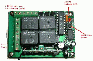
I can not read the connections. Only the 12v.

Look on the actual and give me a pinout.

4 Channel remote control -- posted image.

John DeRosa (Hotwaterwizard)
Stockton California
When in doubt, try it out !
mille 
Member - Posts: 8
Member spacespace
Joined: January 04, 2007
Location: United States
Posted: January 05, 2007 at 12:58 PM / IP Logged  
Theres no instructions with the controls. if you look at the 12v connectors on the side going bottom to top it is a, b, c,  a, b, c, thanks
KPierson 
Platinum - Posts: 3,527
Platinum spaceThis member consistently provides reliable informationspace
Joined: April 14, 2005
Location: Ohio, United States
Posted: January 05, 2007 at 1:36 PM / IP Logged  

A is your common (30)

B is your NO (87)
C is your NC (87A)

You'll need to use two seperate relays for each single actuator.

Wire the common pin to the actuator, wire the NC to ground, and the NO to 12VDC.  This is a standard 5 wire system what will leave both sides of the actuator resting at ground during normal operation.  When either relay is energized it will first remove the ground from the respective leg and then apply 12vdc to that leg, causing the actuator to move.

Good luck

Kevin Pierson
Page of 3

  Printable version Printable version Post ReplyPost New Topic
You cannot post new topics in this forum
You cannot reply to topics in this forum
You cannot delete your posts in this forum
You cannot edit your posts in this forum
You cannot create polls in this forum
You cannot vote in polls in this forum

  •  
Search the12volt.com
Follow the12volt.com Follow the12volt.com on Facebook
Monday, April 29, 2024 • Copyright © 1999-2024 the12volt.com, All Rights Reserved Privacy Policy & Use of Cookies
Disclaimer: *All information on this site ( the12volt.com ) is provided "as is" without any warranty of any kind, either expressed or implied, including but not limited to fitness for a particular use. Any user assumes the entire risk as to the accuracy and use of this information. Please verify all wire colors and diagrams before applying any information.

Secured by Sectigo
the12volt.com spacer
Support the12volt.com
Top
the12volt.com spacer