the12volt.com spacer
icon

2000 nissian sentra remote start


Post ReplyPost New Topic
< Prev Topic Next Topic >
thejushinator 
Member - Posts: 32
Member spacespace
Joined: December 11, 2009
Location: Kentucky, United States
Posted: December 15, 2009 at 8:15 PM / IP Logged  

Ok, I think i get what you are saying tommy.

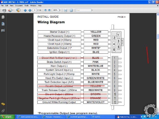
2000 nissian sentra remote start - Page 3 -- posted image.

Above is the wires on the R/S I purchased

Lets say that the car has 2 starter wires and 2 ignition wires. Here is how I would wire the ignition and starter.

The R/S wire yellow is the starter wire, so it would go to the one of the starter wires on the car. But the car has two starter wires. So that means I would take one of the 12 volt input wires from the R/S (red) and connect it to the other starter wire on the car, is this correct ?

The same goes for the ignition. Lets say the car had two ignition wires. I would take the blue iginition wire from the R/S and connect it to one of the ignition wires on the car. Then I would take the other 12 volt input wires from the R/S (red) and hook it to the other ignition wire on the car, is this correct ?

kreg357 
Platinum - Posts: 7,789
Platinum spaceThis member has made a donation to the12volt.com. Click here for more info.spaceThis member has been recognized as an authority in Electrical Theory. Click here for more info.spaceThis member has been recognized as an authority in Mobile Security and Convenience. Click here for more info.spacespace
Joined: January 30, 2009
Location: Pennsylvania, United States
Posted: December 15, 2009 at 8:56 PM / IP Logged  
No.  The two Red wires are inputs TO the R/S.  The R/S start uses those to supply the onboard relays to give the IGN, ACC and Start outputs as well as power itself and control the other functions and outputs ( horn, locks, alarm, etc.).  The extra relays mentioned in an earlier post will be used to supply the cars  additional needs ( ACC2, Start2, etc).  Did you download and review the Ready Remote install guide?   It has some good wiring diagrams of the extra relays sometimes required for a R/S install.  If as T&T says, your car has 1 Start, 1 ACC and 2 IGN's, the G11-xr can handle that without any extra relays.  If the Bulldog info you posted is correct then you will need 2 relays to supply the 2 ACC's and the Ultra Start will handle the 2 Start's with its Selectable (White) output.
Soldering is fun!
thejushinator 
Member - Posts: 32
Member spacespace
Joined: December 11, 2009
Location: Kentucky, United States
Posted: December 15, 2009 at 11:12 PM / IP Logged  

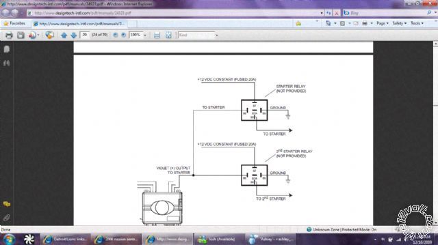
I never even saw that post on page 2. Just went back and looked at that install guide and boy it is like night and day. That has really helped. I looked at the relays in that guide and it helped just a few questions.

2000 nissian sentra remote start - Page 3 -- posted image.

1. The +12 vdc constant (fused 20a), do those go up the constant power (the same place as the two red constant power wires) ? The ground goes to the same spot as the ground as the R/S also i assume.

2. Lets assume I need these when the R/S comes in, what kind of relays do i go to advance auto parts and ask for ?

3. How do i get 20A fuses on the wires that are going to the constant power ?

4. What guage wire do i look for to connect the relays ?

Sorry for all the questions :)

But in all seriousness that install guide on page 2 is AWESOME, has helped me leaps and bounds.

t&t tech 
Platinum - Posts: 2,608
Platinum spacespace
Joined: October 05, 2008
Location: Trinidad and Tobago
Posted: December 16, 2009 at 7:07 PM / IP Logged  

1) Yes

2)Single pole single throw or single pole double throw, doesn't matter!

3)Purchase a blade fuse holder with a couple twenty amp fuses!

4)Purchase relay sockets, these wires will be already suited to the current requirements of the relay!

commit your way to jehovah and he will act in your behalf. psalms 37:5
kreg357 
Platinum - Posts: 7,789
Platinum spaceThis member has made a donation to the12volt.com. Click here for more info.spaceThis member has been recognized as an authority in Electrical Theory. Click here for more info.spaceThis member has been recognized as an authority in Mobile Security and Convenience. Click here for more info.spacespace
Joined: January 30, 2009
Location: Pennsylvania, United States
Posted: December 16, 2009 at 7:40 PM / IP Logged  

Glad to hear the guide helps. 

Basically the output from the R/S actuates the two relays.  This allows for 2 independant and isolated outputs to power the appropriate wires at the cars ignition.

1 Yes  ( If there is only one 12v constant power wire at the cars ignition switch, it was supplying all the power to each of the circuits normally.)

2  12 volt SPDT 30/40 Amp relays  plus the 5 wire harness.  There is a good info section on relays on this site.  I get mine in bulk, prices around $2.25 each, including harness.  Store price for small quanity probably about $9 each...

3  WalMart has inline automotive fuse holders.  You can use the old style Buss glass tube style ( AGC ) or the newer ATC style. ( Might as well get a soldering gun while you are there.)

4  Get the relay with the 5 wire harness.  The wires are the proper guage and usually about 8 to 12 inches long.

On the G11-XR you will be able to get by using the Default options with the possible exception of Menu 2 Opt 1.  That will depend on the Sentra's wiring needs.  Also Menu 2 Opt 4 can be changed to Car Finder.  Set up like that, the # button, when pressed for 3 seconds, will flash the parking lights and beep the horn 5 times.  You will still be able to pop the trunk by holding the UnLock button for 3 seconds.

Your next step is to take a peek in the streeing column at the ignition switch to see if the wires match up to the Bulldog wire list.  And of course, even if they match up exactly, it is wise to test and verify with a DMM.  You might get lucky and not need any extra parts.

Soldering is fun!
thejushinator 
Member - Posts: 32
Member spacespace
Joined: December 11, 2009
Location: Kentucky, United States
Posted: December 18, 2009 at 6:41 PM / IP Logged  

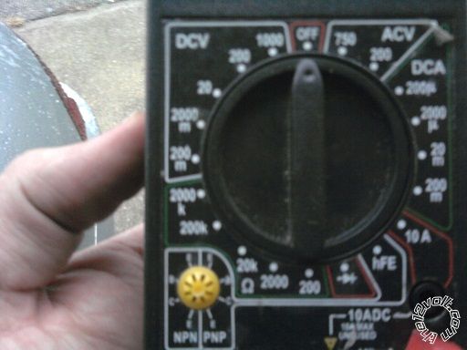
Ok I borrowed a DMM today from a friend of mine. I didn't know which setting to put it on. Here is a picture of it if anyone could help me.2000 nissian sentra remote start - Page 3 -- posted image.

Also I started taking apart the steering column today to check everything out (R/S should be here tomorrow) and there are 6 wires. So it looks like I will be needing to do a relay. Not much extra wire there to pull on so it is going to be tight.

kreg357, could u link me to the relay info on here, I can't seem to find it.

tedmond 
Gold - Posts: 4,610
Gold spaceThis member has been recognized as an authority in Mobile Security and Convenience. Click here for more info.spacespace
Joined: January 06, 2007
Location: Ontario, Canada
Posted: December 18, 2009 at 8:41 PM / IP Logged  

turn the dial to the left under DCV and leave it at 20. Is that digital? if it isnt, sometimes the analogue meters cant read quick enough.

as for relay wiring for additional start, acc, or ign

85 - dedicated (-) function from start/alarm

86 - constant 12v
87 - constant 12v fused @ 20 amps
30 - to wired on car depending on function of (-) output from rs connected to 85.

thejushinator 
Member - Posts: 32
Member spacespace
Joined: December 11, 2009
Location: Kentucky, United States
Posted: December 18, 2009 at 9:12 PM / IP Logged  

Yes it is digital.

Tedmond, the picture above says just one goes to: constant 12v, one to ground, and then one to the wire on the car.......

BTW, u have 85 to dedicated (-) i assume that is the ground ?

kreg357 
Platinum - Posts: 7,789
Platinum spaceThis member has made a donation to the12volt.com. Click here for more info.spaceThis member has been recognized as an authority in Electrical Theory. Click here for more info.spaceThis member has been recognized as an authority in Mobile Security and Convenience. Click here for more info.spacespace
Joined: January 30, 2009
Location: Pennsylvania, United States
Posted: December 18, 2009 at 9:30 PM / IP Logged  

Set the DMM to the DCV 20 position.  This means you are looking for a DC voltage below 20 volts.  Plug the test leads into the Ground and Red jacks.  Test this setup by touching the leads to the cars battery terminals.  You should see around 12.3 volts.  Test leads with aligator clips are handy for checking the Start wire...

The sites Relay section can be found with this link:  https://www.the12volt.com/relays/relays.asp  It has the pin outs and a nice internal diagram of the relay.  Follow the Ready Remote guide for the actual connections to the the Ultra Start and the cars ignition wires.

Remember to allow space for things like Tilt / Telescopic, steering shaft rotation and trim covers in the steering column area.  Don't secure everything until you test.  Tie wraps are the preferred method to position & secure your wires.

After you get all the connections made, insert the R/S's fuses in the red power wires.  The cars parking lights should flash and the horn should beep.  (Parking light and horn connection good )   The 2 transmitters should already be programmed to the G!11.  Next try the Lock and UnLock buttons on the R/S transmitter.  ( Lock and UnLock connections good )  Hold the UnLock button for 3 seconds and the trunk should release.  ( Trunk release good )

At this point you should program the G11's Selectable Output (white wire).  I believe it defaults to IGN but set it for what ever your car needs.  ( Programming will also verify your IGN1 connection )

Before you can do an actual remote start, you must Tach Learn the Ultra Start controller.  Insert the key and turn the switch to ON.  The R/S will turn the cars parking lights on to signal it is doing a tach learn.  Start the car with the key.  Within 20 seconds the parking lights should flash and the horn should beep 3 times to signal a successful tach learn.  ( Good tach signal and Start connection )  Turn the car off and remove the key.  Make sure the hood is closed and press the Start button.  The car should start.  Listen for over / under crank.  Ideally the R/S should be tach learned with a warm engine and you can do that with the Optional Tach Learn procedure outlined in the G11 install guide later.

Do a Key Take Over.  Start car with R/S transmitter,  after the parking lights flash and come on steady insert key and turn to ON. Step on the brake pedal.  The car should continue to run.  Try the Pit Stop function.  With the car running with the key, in park & your foot off the brake, press the R/S start button and then remove the key.  The car should continue to run for 15 minutes.

Next, press the brake pedal with the car running under a remote start.  It should shut down.  Remote start the car again and pop the hood.  It should shut down with the hood open also.  These are important safety features all R/S installs should have.

Have a successful Saturday!

Soldering is fun!
t&t tech 
Platinum - Posts: 2,608
Platinum spacespace
Joined: October 05, 2008
Location: Trinidad and Tobago
Posted: December 18, 2009 at 9:31 PM / IP Logged  

No that 85 isn't dedicated to ground in tedmond's description! That's the trigger for the respective output!

Here's another way

Pin 85- ground

pin 86- To starter wire or accesory

pin 87 - fused twelve volts at 20 amps

pin 30- to the respective wire depending on where you connected 86 (meaning if you were connecting second starter relay, pin 86 would go to the first starter and pin 87 to the second starter) Drawback to this is they will be powered with or without the remote start.

commit your way to jehovah and he will act in your behalf. psalms 37:5
Page of 7

  Printable version Printable version Post ReplyPost New Topic
You cannot post new topics in this forum
You cannot reply to topics in this forum
You cannot delete your posts in this forum
You cannot edit your posts in this forum
You cannot create polls in this forum
You cannot vote in polls in this forum

  •  
Search the12volt.com
Follow the12volt.com Follow the12volt.com on Facebook
Monday, May 20, 2024 • Copyright © 1999-2024 the12volt.com, All Rights Reserved Privacy Policy & Use of Cookies
Disclaimer: *All information on this site ( the12volt.com ) is provided "as is" without any warranty of any kind, either expressed or implied, including but not limited to fitness for a particular use. Any user assumes the entire risk as to the accuracy and use of this information. Please verify all wire colors and diagrams before applying any information.

Secured by Sectigo
the12volt.com spacer
Support the12volt.com
Top
the12volt.com spacer