the12volt.com spacer
icon

side marker wiring


Post ReplyPost New Topic
< Prev Topic Next Topic >
geraldcole 
Member - Posts: 13
Member spacespace
Joined: April 30, 2012
Location: Virginia, United States
Posted: April 30, 2012 at 8:01 PM / IP Logged  

I have a 98 acura integra and I have a single filament side marker that I'm installing.

What I want to accomplish is having the side marker solid with the parking light and blink with the turn signal.

I do NOT want them to blink in sequence. I want to use relays so that the side marker and blinker blinks at the same time.

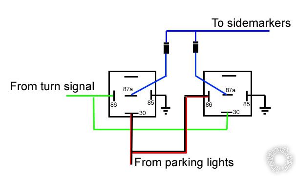
Here's how I have it wired right now (which is not working) for one side marker. The below diagram only allows the side marker to blink when the parking lights and the turn signal is on and it does nothing else.

side marker wiring -- posted image.

howie ll 
Pot Metal - Posts: 16,466
Pot Metal spacespace
Joined: January 09, 2007
Location: United Kingdom
Posted: May 01, 2012 at 3:12 AM / IP Logged  
Your right hand relay is wrong, it should be the same as the left, also the blue wires at 87a should be kept apart with no diodes.
geraldcole 
Member - Posts: 13
Member spacespace
Joined: April 30, 2012
Location: Virginia, United States
Posted: May 01, 2012 at 3:30 AM / IP Logged  
The diagram i showed      was for one side only. If i keep the two blue wires apart then at the side marker i would have those 2 blue wires and a ground there with only a single filament bulb. Also what would be the purpose of having 2 relays hooked up together doing exactly the same thing?
oldspark 
Gold - Posts: 4,913
Gold spacespace
Joined: November 03, 2008
Location: Australia
Posted: May 01, 2012 at 3:35 AM / IP Logged  
Yep, that's a fun "problem".
It can be considered the same as a 'merkan flashing stop light (for indicators) or the old common use of rear indicators as reversing lights.
Each side required DPDT switching (actually 1 SPDT and 1 SPST), and the indicator switch was moved from it's normal before the left/right switch to a relay contact - the switch instead energised whichever side's relay.
Not that any flasher-can is involved in your case.
It can be simply achieved with a similar grounding trick as was done for your fogs (ie, off with high), but that will mean the sides flash out of phase with the front & rear main indicator bulbs.
And that grounding trick may not work if using LED lights...
I have been considering converting my side flashers to also be on as clearance lights, though with that came the thought of having it brighter for flashing (compared to being "non-painfully" bright as a mere parker/clearance light).
And having recently decided to (finally!) get into PICAXEs, I think that's the way to go - especially for the flasher & reverse or stop bulb combination. IMO it's much easier programming a PIC to control an SPDT relay than use a DPDT relay and relocate the flasher can.
I suspect the same PIC solution for the side clearance & flashers. (eg, an 8-pin "08" series PICAXE; ~$3-$4.)
But the above is just a fore-ramble.
I'll search for relevant diagrams that I have and get back to you.
Otherwise I'll actually have to think about the relay/wiring solution.   (I once wrote a lovely 3-pager with figs and the theory etc only to later realise I had it totally R's about. Though I had installed a working 2 DPDT relay solution (for combined rear indicator & reversing lights), when it came to the writeup, I managed to confuse the lot again!)
Incidentally, a J-FET is perfect for this. It works by passing full current UNLESS there is a voltage to reduce or turn it off (aka to pinch it).
Unfortunately they are only low-current devices, nowhere near enough for bulbs (as required for traditional flasher cans).
However, maybe LEDs... hmmm?
Remind me if I don't get back to you (unless someone else posts a solution).
PS - which I think has now been posted...
geraldcole 
Member - Posts: 13
Member spacespace
Joined: April 30, 2012
Location: Virginia, United States
Posted: May 01, 2012 at 3:43 AM / IP Logged  
The 3 situations that the sidemarker should be on are as follows:
Parking lights on: sidemarker solid
Turn signal on: sidemarker blinks at the same time
Parking lights on and turn signal on: sidemarker solid and blinks at the same time as turn signal
geraldcole 
Member - Posts: 13
Member spacespace
Joined: April 30, 2012
Location: Virginia, United States
Posted: May 01, 2012 at 3:54 AM / IP Logged  
The sidemarkers are incandescent not leds so jfet wouldn't send enough juice as you said. And i want them to blink in phase. I don't understand how howie's suggestion would make it work, but with a little clarification with what should be at the sidemarker I can give it a go.
geraldcole 
Member - Posts: 13
Member spacespace
Joined: April 30, 2012
Location: Virginia, United States
Posted: May 01, 2012 at 4:05 AM / IP Logged  
Grats on starting with picaxe controllers they are definitely out of my league [:)]
howie ll 
Pot Metal - Posts: 16,466
Pot Metal spacespace
Joined: January 09, 2007
Location: United Kingdom
Posted: May 01, 2012 at 4:47 AM / IP Logged  
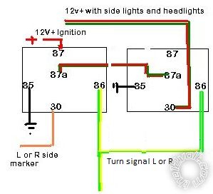
Here's one I just cooked up, Peter, go over it please but as far as I've worked it out,this will give you marker lights solid when lights are on and flashing with indicators when you use them.
With this diagram the side markers will work as required except when you use the hazard flashers.
You can change this by altering the ignition source wire going to 87 on the two left relays to a constant 15amp fuse, although I would start with a 20amp then work down.
I originally used an ignition source as it's safer.
The diodes (1N4004) are MANDATORY. It won't work properly (i.e. separate the sides) without them:-
side_markers.bmp
geraldcole 
Member - Posts: 13
Member spacespace
Joined: April 30, 2012
Location: Virginia, United States
Posted: May 01, 2012 at 7:36 AM / IP Logged  

If I'm reading this right, your diagram could be done without the diodes if you use 2 relays on each side/each side marker (4 total) instead of 3 total. Below I've cropped your diagram to just show 2 relays which would equal just one side marker or one side.

side marker wiring -- posted image.

I've currently hooked it up this way and the only thing that happens is when the running lights are on and you turn the signal on, then the side marker blinks. Otherwise the sidemarker does nothing.

howie ll 
Pot Metal - Posts: 16,466
Pot Metal spacespace
Joined: January 09, 2007
Location: United Kingdom
Posted: May 01, 2012 at 7:42 AM / IP Logged  
Side marker lights should be default wired in with the running (side) lights.
Cost of one relay = cost of 100+ diodes it's a no-brainer.
Page of 3

  Printable version Printable version Post ReplyPost New Topic
You cannot post new topics in this forum
You cannot reply to topics in this forum
You cannot delete your posts in this forum
You cannot edit your posts in this forum
You cannot create polls in this forum
You cannot vote in polls in this forum

  •  
Search the12volt.com
Follow the12volt.com Follow the12volt.com on Facebook
Friday, April 26, 2024 • Copyright © 1999-2024 the12volt.com, All Rights Reserved Privacy Policy & Use of Cookies
Disclaimer: *All information on this site ( the12volt.com ) is provided "as is" without any warranty of any kind, either expressed or implied, including but not limited to fitness for a particular use. Any user assumes the entire risk as to the accuracy and use of this information. Please verify all wire colors and diagrams before applying any information.

Secured by Sectigo
the12volt.com spacer
Support the12volt.com
Top
the12volt.com spacer