Posted: October 04, 2011 at 7:24 AM / IP Logged
Posted: October 04, 2011 at 9:03 AM / IP Logged
Posted: October 06, 2011 at 7:21 PM / IP Logged
Posted: October 06, 2011 at 10:03 PM / IP Logged
Posted: October 06, 2011 at 10:59 PM / IP Logged
Posted: October 08, 2011 at 10:00 PM / IP Logged
Posted: October 09, 2011 at 7:19 AM / IP Logged
Posted: March 15, 2012 at 11:03 AM / IP Logged
Posted: March 19, 2012 at 5:16 AM / IP Logged
Sorry, you can NOT post a reply.
This topic is closed.
 Printable version


| You cannot post new topics in this forum You cannot reply to topics in this forum You cannot delete your posts in this forum You cannot edit your posts in this forum You cannot create polls in this forum You cannot vote in polls in this forum |

| Search the12volt.com |
Follow the12volt.com 
Sunday, December 14, 2025 • Copyright © 1999-2025 the12volt.com, All Rights Reserved • Privacy Policy & Use of Cookies


Sunday, December 14, 2025 • Copyright © 1999-2025 the12volt.com, All Rights Reserved • Privacy Policy & Use of Cookies
Disclaimer:
*All information on this site ( the12volt.com ) is provided "as is" without any warranty of any kind, either expressed or implied, including but not limited to fitness for a particular use. Any user assumes the entire risk as to the accuracy and use of this information. Please
verify all wire colors and diagrams before applying any information.


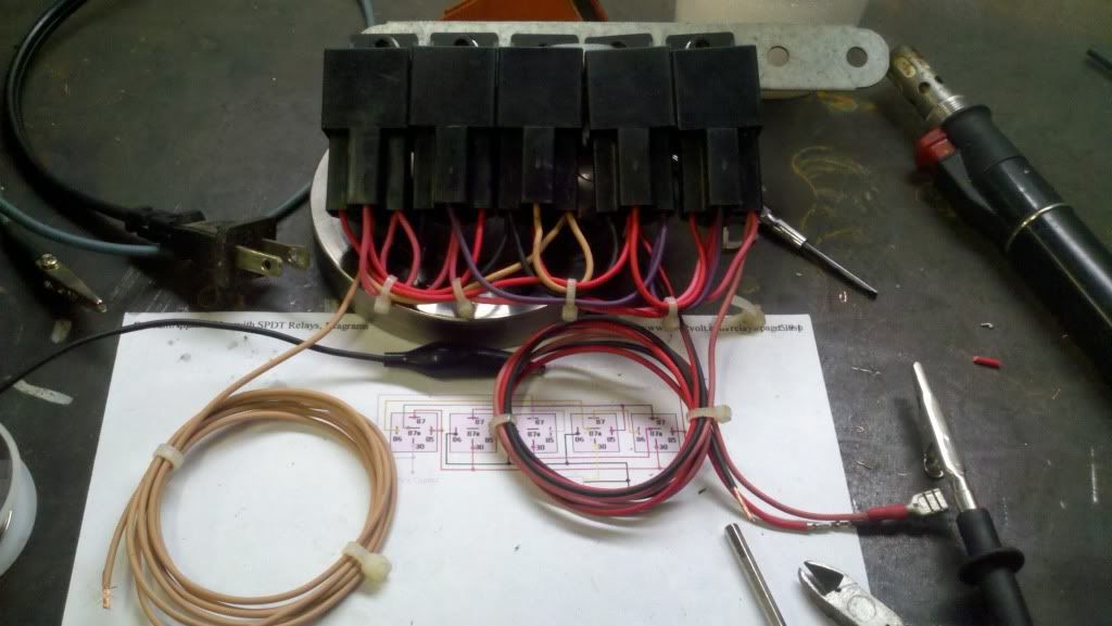
 It IS working, though not as well as I would like. When I power the system up and pulse the input to Gnd, the output latches ON. However, when I pulse the input to Gnd again, it will only latch the output OFF if I pulse it extremely fast. If held for any longer than a fraction of a second, the system will click but stay on.
Is there a remedy to this or is issue inherant to the design? Thanks guys!

 as per
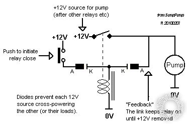
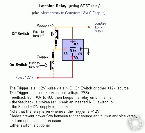
  The diodes are only there to prevent power feeding thru the coil and switch circuit.
The next "physical" diagram shows the above but with the NC feedback switch - ie, push to break feed back hence unlatching the SPST relay - assuming the "push to latch" switch is off.
 The above is simpler if 2 switches can be used.
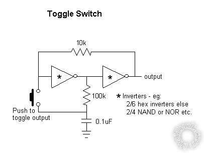
I have used the inverter-gate toggle circuit, but not for relays. Relay coils would probably require a spike-suppression diode, and bear in mind that the inverters or gates themselves may not be powerful enough to source +12V or sink (GND) a relay coil, hence a transistor etc must be added.