the12volt.com spacer
icon

modify to work w/12v input and relay


Post ReplyPost New Topic
< Prev Topic Next Topic >
masik 
Member - Posts: 5
Member spacespace
Joined: October 17, 2007
Posted: September 26, 2008 at 4:11 PM / IP Logged  
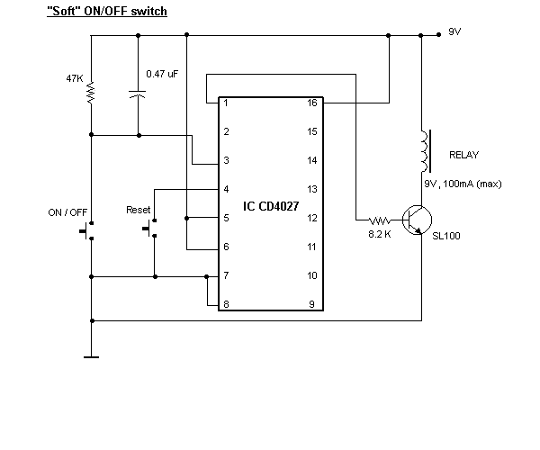
Would someone please modify this to work with 12V input and relay.
Thank you.
modify to work w/12v input and relay -- posted image.
n2ixk 
Member - Posts: 22
Member spacespace
Joined: September 04, 2008
Location: New Jersey, United States
Posted: September 26, 2008 at 4:23 PM / IP Logged  
Replace the relay with a unit having a 12V coil, and you should be good to go. CMOS logic chips (like the 4027) will operate over a pretty wide voltage range (typically 3 to 15V). I would suggest adding a suppressor diode across the relay coil to protect the transistor from spikes. A 1N4001 with the anode at the transistor end of the coil would do just fine.
What exactly is this circuit supposed to do? I can't see how a circuit using a relay output can function as a "soft" switch (assuming that means a device that slowly fades a light on and off).
masik 
Member - Posts: 5
Member spacespace
Joined: October 17, 2007
Posted: September 26, 2008 at 4:51 PM / IP Logged  
Thank you, I got the schematics of this website. http://electronicsworId.tripod.com/designimages/designckt1.html
n2ixk 
Member - Posts: 22
Member spacespace
Joined: September 04, 2008
Location: New Jersey, United States
Posted: September 26, 2008 at 5:06 PM / IP Logged  
OK, this is just what I thought it was--a "push on/push off" switch. Not really a "soft on/off" circuit at all.
BTW, you could eliminate the reset button by hanging an RC network from pin 4 to ground, and charging it with another resistor to +12V. That way, the reset pin is momentarily held "low" at power up, and the flip-flop starts in a predictable state.
masik 
Member - Posts: 5
Member spacespace
Joined: October 17, 2007
Posted: September 27, 2008 at 5:34 PM / IP Logged  
Just to make sure i'm reading the schematic right, bottom right going up the button is ground. And also to replace the reset button, you said just put a resistor instead. 6what size and its pin 4 through res to ground? Thanks
masik 
Member - Posts: 5
Member spacespace
Joined: October 17, 2007
Posted: September 27, 2008 at 5:35 PM / IP Logged  
bottom left sorry of the schematic
n2ixk 
Member - Posts: 22
Member spacespace
Joined: September 04, 2008
Location: New Jersey, United States
Posted: September 27, 2008 at 6:23 PM / IP Logged  
Yes, the symbol at the bottom left denotes ground (European notation).
To replace the reset switch, you need 3 components. First, a resistor and capacitor in parallel, from pin 4 to ground. .47uF and 10Kohm might be a good starting point. Then you need a separate resistor (1K might be a good start) from pin 4 to +12V. All of these values may need to be tweaked around to get a good reliable reset action. The only caveat is that the ratio of the 2 resistor values (which effectively form a series voltage divider) must be sufficient that the cap charges to a logical high at pin 4. At a Vdd of 13.8V, You will need around 11V or so.
What you are doing is forcing pin 4 to be held low by the initial charging of the capacitor when power is first applied, resetting the flip-flop. The cap charges through the 1K resistor until the voltage becomes a logical "high", at which time the flip-flop will function. The 10K resistor in parallel provides a discharge path for the capacitor when the circuit is powered down.

Sorry, you can NOT post a reply.
This topic is closed.

  Printable version Printable version Post ReplyPost New Topic
You cannot post new topics in this forum
You cannot reply to topics in this forum
You cannot delete your posts in this forum
You cannot edit your posts in this forum
You cannot create polls in this forum
You cannot vote in polls in this forum

  •  
Search the12volt.com
Follow the12volt.com Follow the12volt.com on Facebook
Friday, April 19, 2024 • Copyright © 1999-2024 the12volt.com, All Rights Reserved Privacy Policy & Use of Cookies
Disclaimer: *All information on this site ( the12volt.com ) is provided "as is" without any warranty of any kind, either expressed or implied, including but not limited to fitness for a particular use. Any user assumes the entire risk as to the accuracy and use of this information. Please verify all wire colors and diagrams before applying any information.

Secured by Sectigo
the12volt.com spacer
Support the12volt.com
Top
the12volt.com spacer