the12volt.com spacer
icon

98 Hombre/S10 Passlock 2


Post ReplyPost New Topic
< Prev Topic Next Topic >
canter6 
Member - Posts: 16
Member spacespace
Joined: October 09, 2008
Location: Georgia, United States
Posted: October 10, 2008 at 8:02 AM / IP Logged  

98 Hombre/S10 Passlock 2 - Page 2 -- posted image.

canter6 
Member - Posts: 16
Member spacespace
Joined: October 09, 2008
Location: Georgia, United States
Posted: October 10, 2008 at 8:04 AM / IP Logged  
98 Hombre/S10 Passlock 2 - Page 2 -- posted image.
canter6 
Member - Posts: 16
Member spacespace
Joined: October 09, 2008
Location: Georgia, United States
Posted: October 10, 2008 at 8:06 AM / IP Logged  

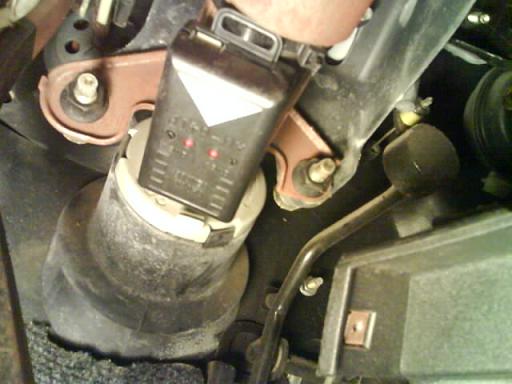
also i found this... it says shock sensor,... doubt its part of my problem.. but hell it cant hurt to get the professionals opinion.

98 Hombre/S10 Passlock 2 - Page 2 -- posted image.

canter6 
Member - Posts: 16
Member spacespace
Joined: October 09, 2008
Location: Georgia, United States
Posted: October 10, 2008 at 8:08 AM / IP Logged  
98 Hombre/S10 Passlock 2 - Page 2 -- posted image.
ckeeler 
Gold - Posts: 1,461
Gold spacespace
Joined: June 20, 2008
Location: New Mexico, United States
Posted: October 10, 2008 at 9:03 AM / IP Logged  

here is the factory wiring. im starting to wonder if after you put this all back together like original, and it still wont start, if maybe you dont really have a bad fuel pump.....???

12 VOLT CONSTANT

RED (+)

IGNITION SWITCH HARNESS

  
 STARTER YELLOW(+)  IGNITION SWITCH HARNESS   
 STARTER 2 N/A   
 IGNITION 1 PINK(+) IGNITION SWITCH HARNESS  
 IGNITION 2 WHITE (+) See NOTE *4 IGNITION SWITCH HARNESS   
 IGNITION 3 N/A     
 ACCESSORY /HEATER BLOWER 1 ORANGE (+)  IGNITION SWITCH HARNESS   
 ACCESSORY /HEATER BLOWER 2 N/A     
 KEYSENSE N/A     
 PARKING LIGHTS ( - ) WHITE (-)  @ BCM, IN LIGHT BLUE PLUG, See NOTE *1   
 PARKING LIGHTS ( + ) BROWN (+)  @ BCM, IN LIGHT BLUE PLUG, See NOTE *1   
 POWER LOCK LIGHT BLUE (TYPE A)  @ BCM, IN BROWN PLUG, See NOTE *1   
 POWER UNLOCK WHITE (TYPE A)  @ BCM, IN BROWN PLUG, See NOTE *1   
 LOCK MOTOR WIRE GRAY (+)  IN DRIVERS DOOR HARNESS   
 DOOR TRIGGER See NOTE *2  @ BCM, See NOTE *1   
 DOMELIGHT SUPERVISION TAN (-)  @ BCM, See NOTE *1   
 TRUNK RELEASE BLACK (-)  @ BCM, IN PURPLE PLUG, See NOTE *1   
 SLIDING POWER DOOR N/A     
 HORN BLACK (-)  @ BCM, IN PURPLE PLUG, See NOTE *1   
 TACH WHITE  @ PCM, See NOTE *3   
 WAIT TO START LIGHT N/A     
 BRAKE WHITE (+)  @ SWITCH ABOVE BRAKE PEDAL   
 FACTORY ALARM DISARM  LIGHT GREEN (-)  @ BCM, IN PURPLE PLUG, See NOTE *1   
 ANTI-THEFT YELLOW (+), ORANGE / BLACK (-) and RED / WHITE (Not used)  GM's PASSLOCK 2 System, these wires exit the Ignition Switch Tumbler together and are in the Main Ignition Switch Harness in the Column.
canter6 
Member - Posts: 16
Member spacespace
Joined: October 09, 2008
Location: Georgia, United States
Posted: October 10, 2008 at 10:21 AM / IP Logged  

thanks, ive got that sheet...

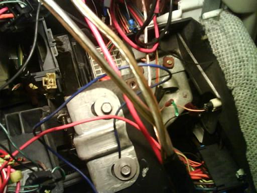
if you look at the pic in the firast post of this page (page 2) you will see a blue and orange wire coming out from behind where the BCM is located.. i can find where that was supposed to be from.. or where it was cut from..

the reason i believe it to be passlock related is the vehicle started up perfectly and ran everytime, BEFORE the battery died..

which is why i traced the yellow data wire from the cylinder down the column.. and couldnt find where there had been a break in it.. (aside from the one i put in last last in an attempt to tie in resistors..

i have gotten the truck to start and stay running twice now ... once drove it around the neighborhood... and shut it off.. then no restart.

also the security light sometimes flashes sometimes not..

there is a set of relays wired in.. BUT these are going to the door popper.. when i powered them up i could hear the popper click in the door.

im not sure what info.. i will need to post up, so if you have a question, ask and ill answer as fully as possible..

im no stranger to working on cars/trucks... but electrical stuff isnt my forte'.... AT ALL. : )

canter6 
Member - Posts: 16
Member spacespace
Joined: October 09, 2008
Location: Georgia, United States
Posted: October 10, 2008 at 10:28 AM / IP Logged  
sorry that was supposed to read CANNOT find where the blue and orange wires were cut from
canter6 
Member - Posts: 16
Member spacespace
Joined: October 09, 2008
Location: Georgia, United States
Posted: October 10, 2008 at 10:32 AM / IP Logged  
btw what is note *1 (im referring to the location of wires sheet you posted) or where can i find this note.
ckeeler 
Gold - Posts: 1,461
Gold spacespace
Joined: June 20, 2008
Location: New Mexico, United States
Posted: October 10, 2008 at 10:58 AM / IP Logged  

NOTE *1 THE BCM (BODY CONTROL MODULE) IS LOCATED TO THE RIGHT OF THE GAS PEDAL BELOW THE RADIO.THE PLUGS ON THE BCM FACE TOWARDS THE DRIVERS SIDE.

NOTE *2 USE TAN (-) FOR THE DRIVERS DOOR LOCATED IN PIN B4 OF THE PURPLE PLUG.USE ORANGE (-) FOR THE PASSENGER DOOR LOCATED IN PIN B2 OF THE PURPLE PLUG,MUST DIODE ISOLATE THE WIRES.
NOTE *3 THE PCM (POWERTRAIN CONTROL MODULE) IS LOCATED ON THE PASSENGER FENDER.ON THE 2.2 LITER THE WIRE IS IN A BLACK 80 PIN PLUG PIN 10,AND ON THE 4.3 LITER THE WIRE IS IN A RED 32 PIN PLUG PIN 20.
NOTE *4 IMPORTANT!!!!! THIS WIRE MUST BE CONNECTED AS IGNITION #2 FOR REMOTE STARTING!!!!!

SORRY, i dont know why i forgot to include that

canter6 
Member - Posts: 16
Member spacespace
Joined: October 09, 2008
Location: Georgia, United States
Posted: October 10, 2008 at 11:08 AM / IP Logged  

thank you.

i was hoping there would be something in that note that could pull my head outta my rear.. and give me a new avenue to go down..

Page of 3

  Printable version Printable version Post ReplyPost New Topic
You cannot post new topics in this forum
You cannot reply to topics in this forum
You cannot delete your posts in this forum
You cannot edit your posts in this forum
You cannot create polls in this forum
You cannot vote in polls in this forum

  •  
Search the12volt.com
Follow the12volt.com Follow the12volt.com on Facebook
Sunday, July 13, 2025 • Copyright © 1999-2025 the12volt.com, All Rights Reserved Privacy Policy & Use of Cookies
Disclaimer: *All information on this site ( the12volt.com ) is provided "as is" without any warranty of any kind, either expressed or implied, including but not limited to fitness for a particular use. Any user assumes the entire risk as to the accuracy and use of this information. Please verify all wire colors and diagrams before applying any information.

Secured by Sectigo
the12volt.com spacer
Support the12volt.com
Top
the12volt.com spacer