the12volt.com spacer
icon

have i blown my amplifier?


Post ReplyPost New Topic
< Prev Topic Next Topic >
i am an idiot 
Platinum - Posts: 13,670
Platinum spaceThis member consistently provides reliable informationspace
Joined: September 21, 2006
Location: Louisiana, United States
Posted: October 21, 2008 at 9:59 PM / IP Logged  
Are you sure that the radio was turned on? With the radio turned on check voltage on the remote wire. Pin 8 and 12 should have near 12 volts on them.
Disconnect the amp and set your meter to ohms and check from the ground terminal to pin 7. It should show a dead short.
ncchance 
Member - Posts: 39
Member spacespace
Joined: June 17, 2008
Location: North Carolina, United States
Posted: October 21, 2008 at 10:09 PM / IP Logged  
Oh yeah, the radio was definitely turned on. It is likely I didn't have a good connection somewhere. I'll check it tomorrow morning once I get to work. I'm thinking I'll have some readings for you before or around 9. I'll probably have to run into the office for a moment. Once again, I appreciate your patience and working with me like you are. Its mighty cool of you.
"I've only gotten this far because I'm known for making every project 10x more difficult than it ever needed to be."
ncchance 
Member - Posts: 39
Member spacespace
Joined: June 17, 2008
Location: North Carolina, United States
Posted: October 22, 2008 at 4:35 PM / IP Logged  
One thing I know is that I need a new job...BADLY!
The pin 7 showed 0.3 ohms from the ground terminal with the amp disconnected. Something very strange that I came across (b/c I don't know a damn thing) is that when everything but the remote is disconnected from the bad amp and I touch the black lead to the ground terminal of my good amp I get 11.84 volts on pins 8 and 12 on the bad amp (using the red lead of course; I'm just trying to be as thorough as possible in explaining what I do on my end) What that mean? Also, not trying to question you in any way whatsoever, but the amp came with two 30 amp fuses in it. Would I not want to use one 30 amp fuse while running these tests? Just throwing that out there just in case. Like I said, you know what you're doing...and I don't know what I am F-ing up. I do some work with disadvantaged children until 9 tonight. I'll be able to respond to any questions you might have or be able to do anything need me to do after that.
"I've only gotten this far because I'm known for making every project 10x more difficult than it ever needed to be."
i am an idiot 
Platinum - Posts: 13,670
Platinum spaceThis member consistently provides reliable informationspace
Joined: September 21, 2006
Location: Louisiana, United States
Posted: October 22, 2008 at 5:19 PM / IP Logged  

With only remote connected to that amp, and your radio on, if you use the other amp's ground as a reference, you should get 12 volts on anything and everything in the Orion amp.  12 volts going in via the remote wire, the voltage goes everywhere looking for ground.  It can not find ground because the amp is not grounded.  12 volts should be everywhere.   The reason for the single 10 amp fuse was incase you accidentally touched pins 10 and 11 at the same time you would have turned the power supply transistors on wide open.  They would last about a half of a second in this state.  They would not blow 60 amps worth of fusing before they failed.

How are you at soldering?   Can you put your meter on ohms and verify that pin 8 and 12 are connected together.   Also check from 11 to 12.    Do you have an old IDE or Floppy ribbon cable that you can cut up to use one of the wires so we can make a jumper?

ncchance 
Member - Posts: 39
Member spacespace
Joined: June 17, 2008
Location: North Carolina, United States
Posted: October 22, 2008 at 11:22 PM / IP Logged  
That was an awesome explanation, it actually made sense to me. Thanks for looking out. I'm pretty good at soldering. I've had a lot of practice recently. Not that you asked, but in case it were to come up, I've never de-soldered before, but I can always get help with that. From what I understand there is more to it than just heating up the solder and pulling a component off a board.
Unfortunately, I'll have to let you know about the 8 to 12 and 11 to 12 readings tomorrow.
Hopefully this pic I uploaded actually shows up correctly. This is on the back of a laptop keyboard. Would that suffice to get a jumper from. I also have an old camera phone I can bust open. I really don't even mind running over to RadioShack and picking up some jumper wires tomorrow afternoon.
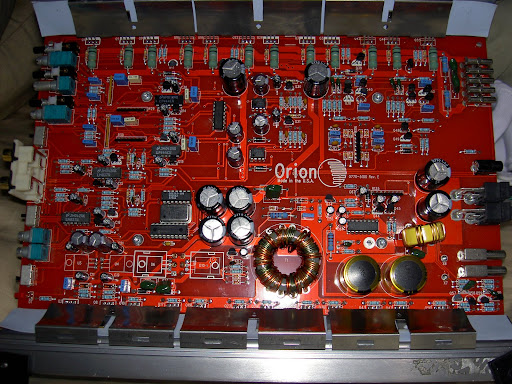
I also added a pic of the amp, I have some closer, more detailed pics. I'm just throwing it out there in case you wanted to give me a reference at any point.
have i blown my amplifier? - Page 4 -- posted image.
"I've only gotten this far because I'm known for making every project 10x more difficult than it ever needed to be."
i am an idiot 
Platinum - Posts: 13,670
Platinum spaceThis member consistently provides reliable informationspace
Joined: September 21, 2006
Location: Louisiana, United States
Posted: October 23, 2008 at 6:03 AM / IP Logged  

The ribbon cable on the laptop keyboard is not what you need for this task.  If you have to buy something, buy an IDE hard drive cable.  It will have 40 or 80 actual wires that you can use.   A 40 conductor harness will probably be a better choice for this job.  If pins 8  11 and 12 are all connected together, you need only 1 jumper.  If 11 and 12 are not connected together, (you will still need only one jumper) you will need to connect the jumper to both of those pins.   Cut the end off of the longest section of the ribbon cable and strip 1 of the 40 strands from the cable.  Strip each end of the cable back about 1/8 of an inch.  Heat up your iron and apply solder to both ends of the wire.  If 8 11 and 12 are all connected together via the circuit board, it will be safer to solder to pin 8, you can get to the end of the chip and should have no chance of bridging it to pin 7.  That would not be good.  8 is power and 7 is ground.  Heat up pin 8 and apply some solder to the pin.  Now that there is solder on each surface, place the jumper wire against pin 8 and heat both surfaces.  The wire will heat up, you need to be holding it back about 6 inches.  Once the solder melts on the wire and the pin, remove the heat and keep the wire in place as long as you can without burning your fingers.  Once the solder has cooled, gently tug on the wire to make sure it is connected good.   If 11 and 12 are not connected together, you will have to put the jumper on both of those pins.  Apply solder to both of those pins, place the jumper between the 2 pins, heat, melt and remove heat, tug on wire after it has cooled.   If 8 11 and 12 are common Just do 8.  It is much safer.

Remember only 1   10 amp fuse.    Plug up the power harness only.  No RCA no speaker terminals  just power.   Now briefly touch the other end of the jumper to the power block, notice if the light comes on,  if it does come on next time leave it on for a couple seconds.  If it remains on for a couple seconds and does not blow the fuse, connect the RCA and speaker connector and see if it plays.  Play it at low volume only, the 10 amp fuse will not go far.  If it plays at low volume we know that the power supply is OK, all we need to do now is figure out which transistor in the path between the remote terminal and the 494 is bad.  Let me know what you figure out.

ncchance 
Member - Posts: 39
Member spacespace
Joined: June 17, 2008
Location: North Carolina, United States
Posted: October 23, 2008 at 3:55 PM / IP Logged  
Before I go buy a new IDE cable let me ask you this. Would it be possible to use a standard serial cable? The reason I ask is because I have several of these just laying around.
"I've only gotten this far because I'm known for making every project 10x more difficult than it ever needed to be."
daburrrninator 
Member - Posts: 31
Member spacespace
Joined: September 17, 2008
Posted: October 23, 2008 at 5:00 PM / IP Logged  
I havent read the entire thread, but if its just being used as a jumper then yes, a serial cable is fine. You could also use cat5 cable if you have any, that makes great jumper wire.
i am an idiot 
Platinum - Posts: 13,670
Platinum spaceThis member consistently provides reliable informationspace
Joined: September 21, 2006
Location: Louisiana, United States
Posted: October 23, 2008 at 5:51 PM / IP Logged  
Yes as stated above the serial cable will be fine. 
haemphyst 
Platinum - Posts: 5,054
Platinum spaceThis member has been recognized as an authority in Electrical Theory. Click here for more info.spaceThis member has been recognized as an authority in Mobile Audio and Video. Click here for more info.spacespace
Joined: January 19, 2003
Location: Michigan, Bouvet Island
Posted: October 23, 2008 at 8:06 PM / IP Logged  
i am... (and I mean this with all sincerity) you are AWESOME, man! I have seen you help several people repair different electronics long-distance, and I have to tell you, that is one of the coolest things I have ever seen! You are a super asset to this forum! Thanks for joining us!
It all reminds me of something that Molière once said to Guy de Maupassant at a café in Vienna: "That's nice. You should write it down."
Page of 6

  Printable version Printable version Post ReplyPost New Topic
You cannot post new topics in this forum
You cannot reply to topics in this forum
You cannot delete your posts in this forum
You cannot edit your posts in this forum
You cannot create polls in this forum
You cannot vote in polls in this forum

  •  
Search the12volt.com
Follow the12volt.com Follow the12volt.com on Facebook
Wednesday, May 1, 2024 • Copyright © 1999-2024 the12volt.com, All Rights Reserved Privacy Policy & Use of Cookies
Disclaimer: *All information on this site ( the12volt.com ) is provided "as is" without any warranty of any kind, either expressed or implied, including but not limited to fitness for a particular use. Any user assumes the entire risk as to the accuracy and use of this information. Please verify all wire colors and diagrams before applying any information.

Secured by Sectigo
the12volt.com spacer
Support the12volt.com
Top
the12volt.com spacer