the12volt.com spacer
icon

have i blown my amplifier?


Post ReplyPost New Topic
< Prev Topic Next Topic >
stevdart 
Platinum - Posts: 5,816
Platinum spaceThis member has made a donation to the12volt.com. Click here for more info.spaceThis member has been recognized as an authority in Mobile Audio and Video. Click here for more info.spaceThis member consistently provides reliable informationspace
Joined: January 24, 2004
Location: Pennsylvania, United States
Posted: October 23, 2008 at 10:13 PM / IP Logged  

(re: haemph's post above)

I am an idiot gets my vote for platinum, too, along with the have i blown my amplifier? - Page 5 -- posted image..  I learn something every time I read his answers. 

Build the box so that it performs well in the worst case scenario and, in return, it will reward you at all times.
ncchance 
Member - Posts: 39
Member spacespace
Joined: June 17, 2008
Location: North Carolina, United States
Posted: October 24, 2008 at 1:17 AM / IP Logged  

I have to agree over and over again. You should be compensated vast sums of money for the invaluable experience and wealth of knowledge you've shared over the years. I've read and relied upon your responses even before our current  correspondence.

Pins 11 and 12 were connected to eachother, but they weren't connected to pin 8. However, I feel like they are common now. The picture below should show what I was able to do based upon my understanding of what you wanted me to do. I have a feeling I may have messed up...which is why I'm not going to put it back in the car until I get your vote of approval. Regardless of which 3 I test, they all check out at .3 ohms on the meter and are all well connected. Tomorrow I'll clean the board off real well and make the connections as you directed. I know I won't mess those steps up. 

http://picasaweb.google.com/Chance.Lester/QuickPics#5260600055381379522

http://picasaweb.google.com/Chance.Lester/QuickPics#5260599966006935074

"I've only gotten this far because I'm known for making every project 10x more difficult than it ever needed to be."
i am an idiot 
Platinum - Posts: 13,670
Platinum spaceThis member consistently provides reliable informationspace
Joined: September 21, 2006
Location: Louisiana, United States
Posted: October 24, 2008 at 3:07 AM / IP Logged  
STOP those are not pins 11 and 12      Go back and look at the picture I drew.    Just wanted to get that out there as soon as I could. Now I am going to have to go to the previous page and find out what I missed.
i am an idiot 
Platinum - Posts: 13,670
Platinum spaceThis member consistently provides reliable informationspace
Joined: September 21, 2006
Location: Louisiana, United States
Posted: October 24, 2008 at 3:14 AM / IP Logged  
haemphyst wrote:
i am... (and I mean this with all sincerity) you are AWESOME, man! I have seen you help several people repair different electronics long-distance, and I have to tell you, that is one of the coolest things I have ever seen! You are a super asset to this forum! Thanks for joining us!
Wow thanks for the kudos, I really appreciate it, but boy you sure know how to put somebody on the spot. We don't even have the amp working yet.
Thank you too, Steve
i am an idiot 
Platinum - Posts: 13,670
Platinum spaceThis member consistently provides reliable informationspace
Joined: September 21, 2006
Location: Louisiana, United States
Posted: October 24, 2008 at 3:21 AM / IP Logged  
NC   Stop again, thanks to your picture I just noticed something, See the 2 identical resistors directly beyond the end of the chip? One of the legs of one goes to pin 8? I am guessing that the other resistor feeds pin 11. check with your meter to confirm this. If the other resistor is connected to pin 11, we need to power pin 12 and the other end of those 2 resistors. Notice that they are connected to each other on the other end. Pin 12 and the ends of the resistors that have the trace connecting them together.
i am an idiot 
Platinum - Posts: 13,670
Platinum spaceThis member consistently provides reliable informationspace
Joined: September 21, 2006
Location: Louisiana, United States
Posted: October 24, 2008 at 3:39 AM / IP Logged  
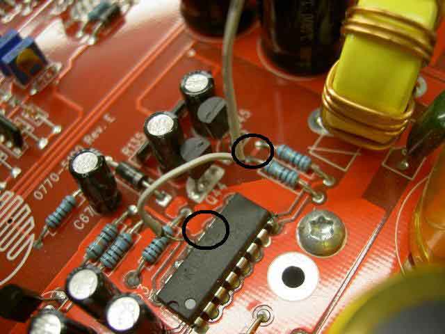
I circled 11 and 12, but remember we only need 12 and the common leg of the resistors, If of course the other end of one of the resistors is connected to 11. I am sure it will be. You did a very nice job on the soldering. In order to remove the solder from 12 and 13, there is no need to get any desoldering braid, you only need to strip a few inches of wire, twist it to keep the wire from pressing flat when you press on it, place the wire along the side of the chip, heat the wire that is right on pins 12 and 13, as the wire gets saturated with solder, pull it towards you so that a clean piece is on those pins, repeat until you have removed the solder that is bridging those pins.
The pic below tells you where to install the jumpers. Run the 2 wires to the resistors and the short one to pin 12. It is easier to put more wires on the resistors than on the chip.
have i blown my amplifier? - Page 5 -- posted image.
ncchance 
Member - Posts: 39
Member spacespace
Joined: June 17, 2008
Location: North Carolina, United States
Posted: November 02, 2008 at 9:27 AM / IP Logged  

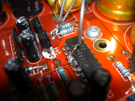
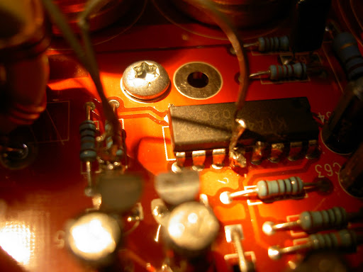
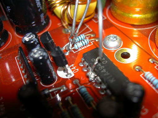
Once again, I greatly apologize for the delay. But at least now you know why. I just attempted to embed some pics I took of the recent soldering. Sorry, they aren't the bext quality. Nothing is being bridged although it may look like it is from the pics I've posted. I'm hoping I didn't misunderstand your directions. I've had a lot on my mind and confusion has tended to set in lately. I haven't and will not hook anything up until I get the go-ahead from you. I'll be back in Durham (home) sometime early this evening and I'll be able, if directed, to hook it up and get any necessary readings.

have i blown my amplifier? - Page 5 -- posted image.

have i blown my amplifier? - Page 5 -- posted image.

have i blown my amplifier? - Page 5 -- posted image.

"I've only gotten this far because I'm known for making every project 10x more difficult than it ever needed to be."
i am an idiot 
Platinum - Posts: 13,670
Platinum spaceThis member consistently provides reliable informationspace
Joined: September 21, 2006
Location: Louisiana, United States
Posted: November 02, 2008 at 10:03 AM / IP Logged  

All looks fine there.  As you stated, in one pic it does look as though 12 and 13 are bridged, the other pic shows they are not.

You can bring it to the car and remember a single 10 amp fuse, and only connect the power plug.  No RCA jacks.  With the power plug connected, briefly touch the jumper to the power block or the shiny metal going into the back of the fuse holder.  By briefly, I mean about 1/2 of a second,  watch the LED when you do this.  It should light up.  If it lights up and the fuse is ok, the next time try it for a few seconds.  If that goes well, connect RCAs and speaker terminal.  With the volume turned very low touch the jumper to the fuse again and see if the sub plays.  If it plays, this will let us know that there is no major damage. 

Let me know if it plays.

Edit:  A soldering tip for you.  When attempting to solder a wire to another component or to another wire for that matter, heat up the wire and apply solder to that device,  then heat up the other device and saturate it with solder.  With solder on each device, now place the devices together where you wish to make the connection.  Heat up the 2 soldered devices and when the solder melts, remove the iron and hold in place until the joint cools. 

Never touch the solder directly to the iron, the iron is hot enough to make the solder melt, if the part you are soldering is not hot enough to melt the solder, you will not make a good connection.  Depending on the quality of your iron, you may have to briefly touch the solder to the iron to start the melting process, but the metal needs to be hot enough to melt the solder. 

ncchance 
Member - Posts: 39
Member spacespace
Joined: June 17, 2008
Location: North Carolina, United States
Posted: November 03, 2008 at 6:59 AM / IP Logged  

I was able to hook it up as you directed last night and the news I have isn't very good. The only light that was visible was a very faint spark created at the end of the IDE jumper cable whenever I touched it  to the power block. I also tried touching the metal rear of the fuse holder, but there wasn't any life from the power LED. Now that I think about it, I don't recall if there was a spark created on the fuse holder the way there was on the power block. Also, I know you said to connect on the power block so that is all that I connected. Did you want me to connect the remote as well?

I'm guessing there may in fact be major damage? Using your soldering tips, which are greatly appreciated by the way, I will re-solder the connections to make sure my problem isn't just a couple of bad connections. That is if you think it would even be worth it. I'll be able to resume with much better contact and response times starting at this point.

Thank you for your condolences and you're understanding.

"I've only gotten this far because I'm known for making every project 10x more difficult than it ever needed to be."
i am an idiot 
Platinum - Posts: 13,670
Platinum spaceThis member consistently provides reliable informationspace
Joined: September 21, 2006
Location: Louisiana, United States
Posted: November 03, 2008 at 8:40 AM / IP Logged  

See the 2 transistors next to the chip, they are labeled Q44 and Q45.  We need to check them to see if they are shorted.  Put your meter on the diode test function, it should be the only little picture on the choice of selections.  The pic should be similar to this

have i blown my amplifier? - Page 5 -- posted image.

Touch and hold one meter lead to one leg of the transistor, now touch the other lead to the other 2 legs, one at a time of course, and notice the readings.   Do this for both transistors and let me know what you find out.

Page of 6

  Printable version Printable version Post ReplyPost New Topic
You cannot post new topics in this forum
You cannot reply to topics in this forum
You cannot delete your posts in this forum
You cannot edit your posts in this forum
You cannot create polls in this forum
You cannot vote in polls in this forum

  •  
Search the12volt.com
Follow the12volt.com Follow the12volt.com on Facebook
Wednesday, May 1, 2024 • Copyright © 1999-2024 the12volt.com, All Rights Reserved Privacy Policy & Use of Cookies
Disclaimer: *All information on this site ( the12volt.com ) is provided "as is" without any warranty of any kind, either expressed or implied, including but not limited to fitness for a particular use. Any user assumes the entire risk as to the accuracy and use of this information. Please verify all wire colors and diagrams before applying any information.

Secured by Sectigo
the12volt.com spacer
Support the12volt.com
Top
the12volt.com spacer