


rs 1000 in 2001 chevrolet silverado
Home /
the12volt's Install Bay /
Car Security and Convenience / rs 1000 in 2001 chevrolet silverado ( Topic Closed)


Posted: December 08, 2008 at 12:37 AM / IP Logged
 But I am a little confused as to where my starter wires from the remote unit go. So if someone could point me in the right direction, it would be much appreciated.
Truck: 2001 Chevy Silverado LT 5.3L
Wiring info from the install manual.
H1:
Violet - Starter output (this wire wants +12v when ignition is in start only and no voltage when in any other position)
Red (2 wires connected together) - +12v Power input (do i need to seperate these or in there only one wire in the truck to hook it up to?)
Yellow - Ignition 1 ( wants 12 volts when in run or start)
Pink - Ignition 2 ( same as yellow but some vehicles need 2, do I need this one?)
Brown - Accessory ( I understand this connects to orange wire in truck?)
H10:
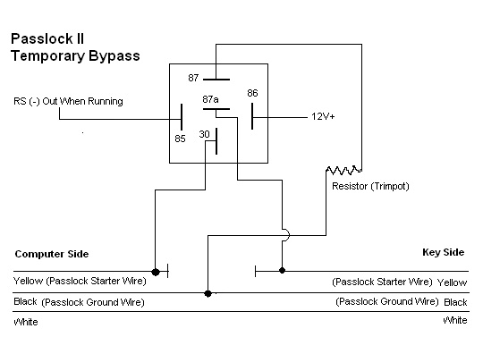
Yellow - (-)200mA Ignition 3 output ( I think this goes to pin 85 on the relay?)
The thing that confusing me is I don't where the wires from H1 go when using the resistor bypass. So if someone could explain where one goes and also where the ones from the relay go, that would be very appreciated.
Thanks,
Bertleaf
But I am a little confused as to where my starter wires from the remote unit go. So if someone could point me in the right direction, it would be much appreciated.
Truck: 2001 Chevy Silverado LT 5.3L
Wiring info from the install manual.
H1:
Violet - Starter output (this wire wants +12v when ignition is in start only and no voltage when in any other position)
Red (2 wires connected together) - +12v Power input (do i need to seperate these or in there only one wire in the truck to hook it up to?)
Yellow - Ignition 1 ( wants 12 volts when in run or start)
Pink - Ignition 2 ( same as yellow but some vehicles need 2, do I need this one?)
Brown - Accessory ( I understand this connects to orange wire in truck?)
H10:
Yellow - (-)200mA Ignition 3 output ( I think this goes to pin 85 on the relay?)
The thing that confusing me is I don't where the wires from H1 go when using the resistor bypass. So if someone could explain where one goes and also where the ones from the relay go, that would be very appreciated.
Thanks,
Bertleaf
Posted: December 09, 2008 at 7:52 PM / IP Logged

Posted: December 09, 2008 at 8:40 PM / IP Logged
Posted: December 09, 2008 at 9:31 PM / IP Logged
Posted: December 09, 2008 at 10:11 PM / IP Logged
Posted: December 09, 2008 at 10:28 PM / IP Logged
Posted: December 10, 2008 at 12:34 AM / IP Logged
Posted: December 10, 2008 at 10:47 AM / IP Logged
Posted: December 10, 2008 at 1:33 PM / IP Logged
Posted: December 11, 2008 at 1:54 AM / IP Logged
 Printable version
| You cannot post new topics in this forum You cannot reply to topics in this forum You cannot delete your posts in this forum You cannot edit your posts in this forum You cannot create polls in this forum You cannot vote in polls in this forum |

| Search the12volt.com |
Follow the12volt.com 
Monday, March 30, 2026 • Copyright © 1999-2026 the12volt.com, All Rights Reserved • Privacy Policy & Use of Cookies

Monday, March 30, 2026 • Copyright © 1999-2026 the12volt.com, All Rights Reserved • Privacy Policy & Use of Cookies
Disclaimer:
*All information on this site ( the12volt.com ) is provided "as is" without any warranty of any kind, either expressed or implied, including but not limited to fitness for a particular use. Any user assumes the entire risk as to the accuracy and use of this information. Please
verify all wire colors and diagrams before applying any information.
