bertleaf wrote:
| Thanks for that information chriswallace187. So if I have it right, the blue wire from H7 would go to the light blue at the BCM and the green on the unit to the white at the BCM.
A few other questions.
1. Where would I hook up the input sensing wire for door locks? And since this is positive trigger, I would use H10/16 and not use H10/17 at all, right? |
|
|
Right on with the lock output wires.
As far as the "door inputs" a bit of clarification - they are used for the
alarm features, and have nothing whatsoever to do with the operation of the power locks, which are operated as a
keyless entry feature. What the "door sensing input" tells the RS-1000 is whether or not any doors are opened, which it uses for alarm triggering as well as possibly for changing the programmed settings.
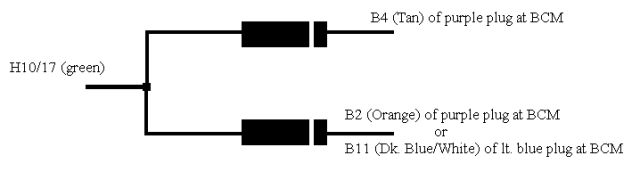
You should use the H10/17 wire, since the "door open" switches are negative. Also, the truck has separate door triggers for the left and right door -
see here for the specific wire colors/locations. You should diode isolate your connections to those wires; you can follow the link to "Mobile Electronics Basics: Diodes" on the left of this site, or just post back for more info on that subject.
bertleaf wrote:
|
2. Factory arm and rearm, is that just what sets off the horn when you open the door without using the electric locks or key doohickey? Do I even need this since I have a security system in the the r/s? From information I have read else where I think I do need it because it is always mentioned but I'm still not clear on what exactly it is. |
|
|
It depends - I'd at least connect the factory disarm because it's just one wire, right at the BCM where you're making other connections anyway. Handy when the factory alarm's been inadvertently armed (if you lock the doors, using the power lock switch or your RS-1000 remote, with a door opened, this will arm the factory alarm).
Factory re-arm is redundant since you've got aftermarket security. It's also slightly more complicated to connect. I'd say don't worry about it.
bertleaf wrote:
|
3. On the relay that came with the r/s, there is a diode across pin 86 and 85. I read here somewhere that this was to prevent voltage spikes or something like that. Do I want to do this to all the relays I'll be using or does it not work in all cases or is it just not required? |
|
|
It doesn't hurt anything to always use a suppression diode such as that. I generally don't bother because I think most of the equipment I install is not that sensitive.
bertleaf wrote:
|
4. Any recommendations on locations to mount the brain and the shock/glass sensor? |
|
|
Brain - behind the instrument cluster or radio/HVAC controls may work if there's room. Make your harnesses look as factory as possible(taped and run alongside the factory wiring is good).
Shock and glass sensor mounting locations are according to the manufacturer of the sensor. I won't comment because I've never done AutoPage
bertleaf wrote:
|
5. Is soldering the best way to connect? Doesn't it crack from temperature changes? Would butt connectors be OK. |
|
|
I like soldering personally, and it doesn't crack when done properly(it's used internally in each of the several dozen OEM control modules on your truck). You may be thinking of a cold solder joint? I'm not sure.
There are several posts on this site about which is better, but both are acceptable when done correctly. Make sure the connections are thoroughly concealed whichever way you go.
bertleaf wrote:
|
Sorry for all the questions but I didn't know there would be quite this much involved or that I know so little.
|
|
|
Your honesty is commendable. There are some people who come in here and think they're entitled to free and quick help and act accordingly. I'm happy to help others get things done. It takes lots of practice to do this stuff very quickly in any case.
C Renner's Auto Electronix
My service is cheap, quick, and good - pick any two


 Topic Closed)


 The H10/3 pink wire is programmable as a factory disarm output. I don't really care for the two-step unlock but I'm not sure if I need the shock sensor bypass output. I don't see where I would use it as the shock sensor has it's own harness with no open wires. Maybe it is for a separate or another shock sensor? The manual just says the wire has a signal 4 seconds before starting and while running, one would assume the unit should do this bypass automatically for it's own shock sensor since a running vehicle is certainly going to vibrate. If that is the case then I will program it to be a factory disarm output and I believe it hooks it up to the lt. green at purple BCM plug.
The wire diagram you linked to has a lock motor, unlock motor, and disarm defeat. I'm not sure what these are, is there any thing else they might be known as? I don't remember seeing them in the install manual. Or maybe I don't need them at all.
I also had a question about the parking light hookups but I don't have my manual with me so I'll have to get that in later.
The H10/3 pink wire is programmable as a factory disarm output. I don't really care for the two-step unlock but I'm not sure if I need the shock sensor bypass output. I don't see where I would use it as the shock sensor has it's own harness with no open wires. Maybe it is for a separate or another shock sensor? The manual just says the wire has a signal 4 seconds before starting and while running, one would assume the unit should do this bypass automatically for it's own shock sensor since a running vehicle is certainly going to vibrate. If that is the case then I will program it to be a factory disarm output and I believe it hooks it up to the lt. green at purple BCM plug.
The wire diagram you linked to has a lock motor, unlock motor, and disarm defeat. I'm not sure what these are, is there any thing else they might be known as? I don't remember seeing them in the install manual. Or maybe I don't need them at all.
I also had a question about the parking light hookups but I don't have my manual with me so I'll have to get that in later.

 Printable version


